background image

XDM-300 Installation and 
Maintenance Manual 

 Equipment 

Installation 


417006-2311-0H3-A00 ECI 

Telecom 

Ltd. 

Proprietary 

3-97 


Connecting Electrical Interfaces through the 
TPU 

The type of cable used to connect the I/O modules to the TPMs depends on the 
type of I/O module being protected, as follows: 

|


For PIM2_21s, 2 x 50 to 1 x 100 SCSI cables are supplied, to be connected 

from four different PIM2_21s to connectors PIM2_21 #1, PIM2_21 #2, 
PIM2_21 #3, and PIM2_21 PROTECT at the bottom of the TPM2_3. 
Multipair traffic cables are connected to the DDF#1, DDF#2, and DDF#3 
connectors at the top of the TPM2_3. 

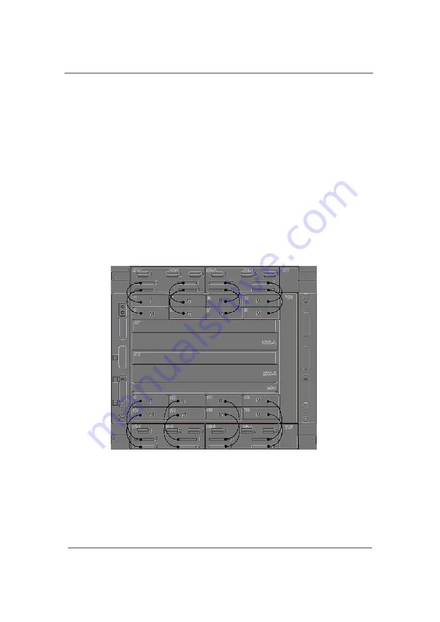
The connection between TPM2_3s and PIM2_21s is shown in the following 
figure. 

Connections are between a connector in the TPM and the corresponding 
module in the shelf, where “P” denotes protection and 1, 2, and 3 are for 
reference purposes. 


Figure 


3-60: XDM-300 1:3 protection scheme example 

|


For PIM345_3 or SIM1_4/E modules, the supplied cables enable 

connection from the DIN 1.0/2.3 connectors on the I/O module to the 8W8 
MAIN and PROTECT connectors at the bottom of the TPM-H_1. The 
traffic coaxial cables are connected to the OUT/IN connectors at the top of 
the TPM-H_1. These connections are shown in the following figure. 


Содержание XDM-300

Страница 1: ...XDM 300 Installation and Maintenance Manual Version 7 417006 2311 0H3 A00...

Страница 2: ......

Страница 3: ...1 Site Preparation 2 4 Tools and Test Equipment 2 6 Installing the XDM 300 in Racks 2 7 Preparing Cables and Fibers 2 14 Work and Equipment Safety 2 20 Data Cables for EISMBs DIOMs and MCSMs 2 28 Prot...

Страница 4: ...bleshooting 4 12 Replacing Cards and Modules 4 20 Replacing RAP Components 4 28 Connectors Pin Assignment A 1 Overview A 1 ECU300 ECU300 F Card Connectors A 2 MXC300 DC Input Power Connectors A 10 PIM...

Страница 5: ...33 Figure 3 1 Components of horizontal XDM 300 installation 3 3 Figure 3 2 Components of XDM 300 vertical installation 3 6 Figure 3 3 XDM 300 typical horizontal installation in an ETSI A rack 3 11 Fig...

Страница 6: ...the filter frame 3 49 Figure 3 34 Filter frame in lower position 3 50 Figure 3 35 Inserting the air filter 3 51 Figure 3 36 XDM 300 shelf and rack grounding 3 52 Figure 3 37 Installing the FCU300 3 5...

Страница 7: ...ng the fiber into the extractor 3 108 Figure 3 72 Pressing extractor s release tab onto SFP s clip 3 108 Figure 3 73 Extracting the LC connector 3 109 Figure 3 74 Moving the connector beyond the tab 3...

Страница 8: ......

Страница 9: ...connectors pin identification A 26 Figure A 14 ALARMS connector pin identification A 28 Figure B 1 Mounting diagrams for ETSI racks B 3 Figure B 2 Mounting diagrams for 19 and 23 racks B 4 Figure B 3...

Страница 10: ...List of Figures XDM 300 Installation and Maintenance Manual viii ECI Telecom Ltd Proprietary 417006 2311 0H3 A00...

Страница 11: ...ation sequence 3 4 Table 3 2 Outline of vertical XDM 300 installation sequence 3 7 Table 3 3 XDM 300 recommended circuit breakers 3 23 Table 3 4 XDM 300 recommended circuit breakers 3 31 Table 3 5 xRA...

Страница 12: ...ent A 8 Table A 6 ETHERNET connectors pin assignment A 9 Table A 7 PIM2_21 receive lines upper connector pin assignment A 11 Table A 8 PIM2_21 transmit lines lower connector pin assignment A 12 Table...

Страница 13: ...also provides task oriented instructions for indications troubleshooting hardware related problems and replacing hardware components cards modules accessories Intended Audience This manual is intende...

Страница 14: ...tion In the Alarms menu Menu Option Selection from a menu or leading to another command Select Update View Objects Italics New terms and emphasized text Examples in text Borders around text Notes caut...

Страница 15: ...verged MSPP and All Range ROADM General Description XDM Small Shelves Reference Manual XDM System Specifications EMS XDM Element Management System User Manual LightSoft Network Management System User...

Страница 16: ...maintains a staff of design engineers and highly trained field service personnel The services of this group are available to customers at any time If you are interested in obtaining design assistance...

Страница 17: ...ier class Ethernet as well as traditional SDH voice centric services Gradual in service capacity expansion based on service provisioning needs An optical connection operating at a specific STM rate ca...

Страница 18: ...r directly on top of the XDM 300 shelf Protection of I O modules in the upper and lower module cages is supported CAUTION When the XDM 300 shelf is to be installed vertically pay attention to position...

Страница 19: ...al Introduction 417006 2311 0H3 A00 ECI Telecom Ltd Proprietary 1 3 I O protection is not supported in this option The XDM 300 shelf can be installed in a horizontal or vertical position Figure 1 2 Ba...

Страница 20: ...300 shelves installed in a horizontal position A TPU mounted on top of the basic shelf protecting the I O modules in the upper module cage A TPU attached under the basic shelf protecting the I O modul...

Страница 21: ...odules in the shelf in a 1 1 1 2 or 1 3 configuration If a failure is detected in one of the operating I O modules the active MXC via the TC module in the TPU switches the traffic from the active I O...

Страница 22: ...Installation and Maintenance Manual 1 6 ECI Telecom Ltd Proprietary 417006 2311 0H3 A00 Figure 1 5 XDM 300 with two TPUs Similar I O protection options are supported for XDM 300 shelves installed in...

Страница 23: ...the basic shelf to add CWDM networking capabilities to the platform The OCU can accept various CWDM modules like Mux DeMux splitters couplers OADMs and power amplifiers Each expansion shelf TPU or OCU...

Страница 24: ...Introduction XDM 300 Installation and Maintenance Manual 1 8 ECI Telecom Ltd Proprietary 417006 2311 0H3 A00...

Страница 25: ...his chapter contains important information to help you carry out safe and trouble free installation Outline of Installation Procedure The main steps involved in the installation of an XDM 300 shelf ar...

Страница 26: ...addition of the TPU TPUs at a later stage 7 When applicable install the EMS XDM management station see the EMS XDM User Manual 8 Install the power distribution and alarm panels xRAP B on page 3 77 or...

Страница 27: ...a different rack Connect coaxial and multipair traffic cables to the electrical I O modules if you are not using a TPU or for modules which are not protected Connect both the electrical I O modules an...

Страница 28: ...site Parameter Compliance requirements Electromagnetic interference FTZ 1TR9 EN 55022 94 EN 50082 1 92 Temperature ETSI ETS 300 19 2 3 Test Spec T3 1 Physical Location WARNING XDM 300 shelves are int...

Страница 29: ...ulated XDM 300 two TPUs OCU 575 443 246 30 1 shelves only 60 fully populated xRAP 100 133 445 185 10 xRAP B 133 445 185 9 5 xDDF 21 44 5 440 150 3 FST 44 5 440 240 5 ODF 44 5 440 240 8 Power Sources X...

Страница 30: ...ncludes tools for the assembly of coaxial cables see the following table and tools for the preparation of optical patch cords Table 2 2 Recommended coaxial cable assembly tools No Name Description 1 S...

Страница 31: ...s Power cables Data cables Timing cables Two ducts on the rack s front rails for routing up to 200 optical fibers Open frame top and bottom for easy routing of cables from suspension floors and or cei...

Страница 32: ...figure 3 Always install the first XDM 300 shelf in the lower part of the rack leaving a space of at least 1U from the bottom of the rack 4 In mixed horizontal and vertical airflow equipment installati...

Страница 33: ...XDM 300 Installation and Maintenance Manual Before You Start 417006 2311 0H3 A00 ECI Telecom Ltd Proprietary 2 9 Figure 2 1 ETSI A rack closed view...

Страница 34: ...stored on the right or left side of the tray Leave at least 50 mm free space between the XDM 300 cabling accessories and its FST and another 50 mm free between the FST and the next XDM 300 shelf Cabl...

Страница 35: ...XDM 300 Installation and Maintenance Manual Before You Start 417006 2311 0H3 A00 ECI Telecom Ltd Proprietary 2 11 Figure 2 2 XDM 300 typical horizontal installation in an ETSI A rack...

Страница 36: ...onal equipment may be installed in the remaining rack space provided that any heat generated by additional equipment can efficiently be dissipated and that thermal isolation is provided between the va...

Страница 37: ...XDM 300 Installation and Maintenance Manual Before You Start 417006 2311 0H3 A00 ECI Telecom Ltd Proprietary 2 13 Figure 2 4 Typical installation of XDM 300 and XDM 1000 shelves in an ETSI A rack...

Страница 38: ...described in Optical Fibers on page 2 18 Data cables for data modules described in Data Cables for EISMBs DIOMs and MCSMs on page 2 28 as applicable Grounding Cables Rack equipment is bonded through t...

Страница 39: ...bution subsystem to the DC input terminals of the rack s RAP panel Two input power cables are required for each rack one for each source The cables must use copper leads complying with UL ETSI recomme...

Страница 40: ...RAP the other end is open and connects to the client s alarm collecting facility Two types of this cable are available xRAP 100 bay alarm cable Connects to the ALARM IN OUT connector on the xRAP 100 x...

Страница 41: ...anced E1 tributary interfaces Electric Traffic Cables Some electric traffic cables can be prepared on site The following table lists the type of cables and mating connectors needed for each XDM 300 tr...

Страница 42: ...of shielded 120 twisted pairs PIM Triple twins of 50 pin SCSI male TPM Twin 136 pin VHDCI male 1 TPMH_1 E3 and DS 3 34 45 Mbps STM 1 electrical RG179x8 multicoaxial cable PIM DIN1 0 2 3 male TPM 8W8 D...

Страница 43: ...r of fiber patch cords per interface LC male 8 fibers SIM1_82 STM 1 optical 1 pair of fiber patch cords per interface LC male 16 fibers SIM4_2 STM 4 optical 1 pair of fiber patch cords per interface L...

Страница 44: ...rfaces only XDM shelves must be installed in accordance with National Electrical Code Do not work on any equipment when it is connected to a voltage source DC or AC except to insert remove cards or mo...

Страница 45: ...the power source in accordance with ETS300132 2 The following figure shows a simplified diagram of the connections to CGND suitable for the installation of XDM shelves Power supply Phase Neutral Groun...

Страница 46: ...ositive than 43 VDC Rack grounding requirements Connect the rack to the site grounding bar with a ground cable according to ETSI recommendations top bottom connection The rack is supplied with a main...

Страница 47: ...s via the mounting brackets The mounting bracket internal surface facing the rails and the equipment must be free of paint and provide electrical continuity to the equipment frame Check the resistance...

Страница 48: ...g of the site This device limits the maximum delivered current to a safe value UL Statutory Warnings and Requirements This section outlines the UL statutory warnings and requirements applicable to XDM...

Страница 49: ...he DC source and the point of connection of the grounding electrode conductor CAUTION Observe the following equipment grounding rules see Grounding Requirements on page 2 21 The equipment has a connec...

Страница 50: ...utions described in this section be sure to observe the following warnings when operating a product equipped with a laser device Failure to observe these warnings could result in fire bodily injury an...

Страница 51: ...25_1PSxx 1466 1615 Single SLM Min 0 Max 5 OTC25_1AIxx 1466 1615 Single SLM Min 0 Max 5 OTR16_I3 1266 1360 Single SLM Min 10 Max 3 OTR16_S3 1260 1360 Single SLM Min 5 Max 0 OTR16_L3 1280 1335 Single SL...

Страница 52: ...interface for GbE 1 2 GbE FE 1 pair of 50 62 5 m MM fiber patch cords per interface for FE LC male EISMB_840 3 4 FE 1 pair of 50 62 5 m MM fiber patch cords per interface LC male 8 fibers EISMB_840 c...

Страница 53: ...port is made as a connection to an electrical interface listed in the following table The following table lists the type of Ethernet electrical traffic cables and the mating connectors needed for the...

Страница 54: ...ge ESD or include sensitive items are identified by the basic ESD warning symbol shown in the following figure Figure 2 8 Basic ESD warning symbol The information provided in this section is in line w...

Страница 55: ...electrostatic discharge or fields and in which the operator is not exposed to additional risks is called an ESD Protected Area EPA Personnel Training During production and assembly equipment is handle...

Страница 56: ...ludes Wrist strap with 1 M series resistor Bonding strap with 1 M series resistor ESD carpet work surface 0 25 m2 minimum The temporary EPA must include temporary controlled work surfaces and or floor...

Страница 57: ...XDM 300 Installation and Maintenance Manual Before You Start 417006 2311 0H3 A00 ECI Telecom Ltd Proprietary 2 33 Figure 2 9 XDM 300 typical temporary EPA arrangement...

Страница 58: ...he operator must be bonded to ground at all times when handling ESDs 4 If it becomes necessary to remove an ESD from equipment and transfer it to a temporary work surface away from the equipment the E...

Страница 59: ...he XDM 300 and auxiliary equipment The procedures for equipment replacement and upgrades are similar to those described for installation of the equipment and when relevant notes regarding live replace...

Страница 60: ...he main equipment used for both installations is similar and differs in the number of accessories type of brackets used in each position and one accessory used only for horizontal mountings NOTE If yo...

Страница 61: ...A high density installation of a horizontal XDM 300 shelf and corresponding accessories might include the equipment illustrated in the following figure The different components are described alongsid...

Страница 62: ...100 or xRAP Cable guides two Cable slack tray Fiber guides for ETSI A racks two FST optional ODF units optional Optical Patch Panel OPP Note Installation of the optional xDDF 21 channel patch panel i...

Страница 63: ...TPMs Triple slot TPMs Installing TPU Modules 9 Install blank covers where I O modules cards and TPMs are not used 10 Route and connect all cables and fibers for ETSI A racks including Power and alarm...

Страница 64: ...e A high density installation of a vertical XDM 300 shelf and corresponding accessories might include the equipment illustrated in the following figure The different components are described alongside...

Страница 65: ...atch panel is implemented as part of the traffic cable routing process Installing Ancillary Units in Racks on page 3 16 4 Prepare the XDM 300 shelf for vertical installation Remove the horizontal inst...

Страница 66: ...Ms Double slot TPMs Triple slot TPMs Installing TPU Modules 10 Install blank covers where I O modules cards and TPMs are not used 11 Route and connect all cables and fibers for ETSI A racks including...

Страница 67: ...packaging material until you are ready to install them The use of an antistatic wrist strap connected to a grounded equipment frame or rack is recommended when handling cards and modules during insta...

Страница 68: ...elecom s Mechanical Department These racks can be installed on wooden concrete or suspended floors or suspended from overhead mountings The XDM 300 can be installed in the rack in an horizontal or ver...

Страница 69: ...clude in addition to the shelf itself ancillary equipment such as RAP cable guides for low order and high order traffic cables fiber guides cable slack tray for cables in the lower section of the XDM...

Страница 70: ...uipment Installation XDM 300 Installation and Maintenance Manual 3 12 ECI Telecom Ltd Proprietary 417006 2311 0H3 A00 Figure 3 4 Typical horizontal installation of two XDM 300 shelves in an ETSI A rac...

Страница 71: ...Installation and Maintenance Manual Equipment Installation 417006 2311 0H3 A00 ECI Telecom Ltd Proprietary 3 13 Figure 3 5 Typical horizontal installation of three basic XDM 300 shelves in 2200 mm ETS...

Страница 72: ...nstallation XDM 300 Installation and Maintenance Manual 3 14 ECI Telecom Ltd Proprietary 417006 2311 0H3 A00 Figure 3 6 Typical horizontal installation of three XDM 300 shelves with TPUs in 2600 mm ET...

Страница 73: ...lation in an ETSI A rack may include in addition to the shelf itself ancillary equipment such as RAP a cable guides for low order and high order traffic cables a fiber guide FST and xDDF 21 patch pane...

Страница 74: ...shelf accessories recommended for installations with a large number of optical modules Installing the Fiber Storage Tray on page 3 34 ODF units Installing the Optical Distribution Frame ODF on page 3...

Страница 75: ...the rack grounding stud 4 Connect DC input power cables to the xRAP B 5 Connect the DC power cables of the XDM 300 shelves to the xRAP B 6 Install circuit breakers 7 Check DC voltage polarity 8 Connec...

Страница 76: ...two or three different points on the lug sleeve using an appropriate crimping tool and die The recommended tools are Panduit CT 720 crimping tool with CD 720 2 die Klauke K18 crimping tool with D50 di...

Страница 77: ...I Telecom Ltd Proprietary 3 19 Figure 3 8 Location of xRAP B grounding stud To connect DC input power cables to the xRAP B 1 Before starting identify the openings used to route power cables to the xRA...

Страница 78: ...igure 3 10 Connecting DC power cables to the xRAP B CAUTION Before connecting the power leads make sure to identify the terminal polarity on the xRAP B power terminal board 4 Bring the two leads of on...

Страница 79: ...the xRAP B board in accordance with the following figure Figure 3 11 Identification of xRAP B connectors 2 Insert the end of the DC power cable terminating with a 5 pin D type male connector near the...

Страница 80: ...the shelves and all other components To install the xRAP B circuit breakers 1 If the xRAP B front panel has not been removed open the two captive screws fastening the xRAP B front cover to its chassis...

Страница 81: ...mended circuit breakers Shelf type Maximum power dissipation Recommended CB per shelf XDM 300 basic shelf 1000 W 3415 BTU hr 50A XDM 300 with TPU 1200 W 4098 BTU hr 50A XDM 300 with two TPUs 1400 W 47...

Страница 82: ...f the alarm monitoring cable intended for shelf 1 to the Shelf 1 connector on the xRAP B 4 Route the alarm cables towards the cable retainers at the rear of the xRAP B see Location of xRAP B grounding...

Страница 83: ...d the negative lead 48 V with a gray cable In the following sections that describe DC power cable connections use cables with appropriate colors to comply with the standards in your area of residence...

Страница 84: ...the installation parts kit To ground the xRAP 100 1 The xRAP 100 grounding stud is located on its bottom cover Use the following figure to identify it 2 If necessary prepare a grounding lead in accord...

Страница 85: ...100 by referring to the following figure Figure 3 14 Identification of xRAP 100 cable routes 2 Open the two captive screws fastening the xRAP 100 front cover and remove the cover 3 Identify the vario...

Страница 86: ...nut Tighten the nut with a torque of 450 N cm to 550 N cm 7 Attach the lug of the black lead to the negative stud terminal marked on the power terminal board 8 Repeat Step 6 for the black lead lug 9 I...

Страница 87: ...connectors simultaneously 3 Fasten the screws of the D type connector 4 If you are connecting additional shelves to the xRAP 100 repeat the above steps for each shelf 5 If an additional power source i...

Страница 88: ...t A of shelf 1 the circuit breaker is included in the installation parts kit supplied with the equipment its rating is in accordance with the ordered shelf configuration The recommended circuit breake...

Страница 89: ...C to 75 VDC and that it has the correct polarity 5 Return all xRAP 100 circuit breakers to OFF 6 Disconnect the xRAP 100 input power sources 7 Reinstall the xRAP 100 front cover and fasten it using th...

Страница 90: ...XDM 300 to help neatly route control timing and management cables connected to the ECU300 ECU300 F card and traffic cables connected to electrical traffic modules in the lower module cage If electrica...

Страница 91: ...Figure 3 19 Fiber guide for ETSI A racks To install the fiber guide in the rack Install the cable guide in the rack one mounting hole above the cable guide and fasten it to the rack side rails with f...

Страница 92: ...the detailed cabling diagrams or tables of each shelf When preparing the fiber refer to the safety information in Work and Equipment Safety on page 2 20 3 Label the cables in accordance with the cabli...

Страница 93: ...ective cap until an optical fiber is connected to the corresponding connector and immediately install a protective cap after a cable is disconnected The minimum bending radius of optical fibers is 35...

Страница 94: ...et to the corresponding ODF side panel with three screws as shown in the following figure Figure 3 22 Attaching rack mount brackets to the ODF To connect optical fibers to the ODF 1 Push the release b...

Страница 95: ...XDM 300 Installation and Maintenance Manual Equipment Installation 417006 2311 0H3 A00 ECI Telecom Ltd Proprietary 3 37...

Страница 96: ...DF first start filling the slots of the lower splice support After the slots are occupied reinstall the top splice support and continue filling the support slots 9 After splicing all the fibers reinst...

Страница 97: ...supports of the ETSI A rack or the rack sidewalls in case of an ETSI B rack 5 Push the button on the front panel of the OPP to release the latch and pull the OPP towards you to open it NOTE The OPP h...

Страница 98: ...ective caps or with the mating cable connector Do not remove the protective cap until an optical fiber is connected to the corresponding connector and immediately install a protective cap after a cabl...

Страница 99: ...or the installation of ECU300 ECU300 F MXC300 and FCU300 cards as described in Installing XDM 300 Cards on page 3 53 I O modules as described in Installing XDM 300 Modules TPMs in the optional TPU as...

Страница 100: ...supplied in the installation kit The procedures required for preparing the XDM 300 for vertical installation follow CAUTION When installing an XDM 300 shelf vertically pay attention to position the s...

Страница 101: ...rtical lower bracket 1 Orient the XDM 300 shelf on a flat clean surface upside down 2 Place the vertical lower bracket on the shelf and fit the holes in the bracket with the corresponding holes in the...

Страница 102: ...311 0H3 A00 To prepare the filter frame assembly 1 Identify the filter frame assembly parts according to the following figure Figure 3 28 Preparing the filter frame assembly 2 Insert the filter frame...

Страница 103: ...ter frame assembly 1 Place the filter frame assembly at the rear of the lower bracket 2 Insert the two front screws of the filter frame into the corresponding latch shaped holes in the bracket Figure...

Страница 104: ...lf to normal position 2 Place the shelf near the edge of the surface to enable the lower bracket to protrude out 3 Place the vertical upper bracket on the shelf and fit the holes in the bracket with t...

Страница 105: ...thumbnuts from the installation kit and fasten them on the screws Figure 3 31 Installing the thumbnuts To attach an XDM 300 shelf in the vertical position to a rack 1 Identify the prescribed position...

Страница 106: ...ing the Air Filter Normally the filter frame is attached in its upmost position by two thumbnuts The frame must be lowered in order to gain access to the filter guides and to install the filter To low...

Страница 107: ...uipment Installation 417006 2311 0H3 A00 ECI Telecom Ltd Proprietary 3 49 2 Lower the filter frame screws to their very lowest position to bring the filter guides in front of the opening in the lower...

Страница 108: ...allation XDM 300 Installation and Maintenance Manual 3 50 ECI Telecom Ltd Proprietary 417006 2311 0H3 A00 The following figure shows the filter frame in the lower position Figure 3 34 Filter frame in...

Страница 109: ...vertical filter 1 Identify the filter s air intake side indicated by two coding tabs 2 Place the filter in front of the slot with the coding tabs facing downward Figure 3 35 Inserting the air filter...

Страница 110: ...ing requirements specified in Grounding Requirements on page 2 21 and Preparing Cables and Fibers Obtain the required materials and make sure to perform the grounding connections in accordance with th...

Страница 111: ...ug must be inserted over both grounding posts Installing XDM 300 Cards After the shelf has been installed and grounded you can install the cards Before you start When installing cards make sure to car...

Страница 112: ...packaging is sealed 2 Remove the FCU300 from its antistatic protection packaging and perform a visual inspection to detect damage during shipping Report any problems 3 Record the hardware version indi...

Страница 113: ...serting or removing a card Always hold the ECU300 ECU300 F by grasping the sides of the card without touching any of the internal electronics or front panel switches and connectors To install the ECU3...

Страница 114: ...ted pull the card out and repeat the procedure 6 Secure the ECU300 ECU300 F in place by tightening the two captive screws MXC300 Card The XDM 300 shelf always operates as redundant platforms therefore...

Страница 115: ...problems 3 Record the hardware and software versions indicated on the card s identification labels 4 Press both brown levers located on the card s extractor handles to release the handles 5 Simultaneo...

Страница 116: ...ce before the connectors are mated pull the card out and repeat the procedure 9 Turn the two extractor handles simultaneously to the horizontal position to lock the card in place 10 Secure the MXC300...

Страница 117: ...nstalling a quad I O card NOTE When quad I O cards or SIM16_1 modules are not installed in slots I17 I18 the openings must be covered with blank panels to avoid cooling air escape and comply with elec...

Страница 118: ...aptive screws 9 Install the SFP XFP transceivers according to Installing SFP XFP transceivers in optical CWDM modules and cards on page 3 65 Installing XDM 300 Modules This section describes the insta...

Страница 119: ...WDM I O modules which are single slot modules The installation of PIM2_63 B and MCSMs which are double slot modules is described in Installing Double Slot Modules on page 3 67 In general to facilitate...

Страница 120: ...g and perform a visual inspection to detect damage during shipping Report any problems 3 Record the hardware and software versions indicated on the module s identification labels 4 Identify the assign...

Страница 121: ...6 Fasten the module to the chassis by tightening the two fastening screws Do not use excessive torque when tightening the screws 7 If you are installing an optical CWDM or mixed module with SFP trans...

Страница 122: ...t been physically damaged during shipment and that the antistatic protection bag of the original packaging is sealed 3 Remove the module from its antistatic protection packaging and perform a visual i...

Страница 123: ...tall SFP XFP transceivers in optical or CWDM I O modules and cards 1 Identify the prescribed position on the module according to the site installation plan 2 Check that the SFP XFP has not been physic...

Страница 124: ...FP transceiver into an I O module CAUTION All slots that are not in use must remain covered If you have to replace a module or card remove the SFP XFP first Installing the OHU module The OHU installat...

Страница 125: ...that all the double slot modules PIM2_63s or MCSMs specified for installation in the XDM 300 shelf in accordance with the shelf installation plan are available Figure 3 45 Installation of typical dou...

Страница 126: ...as not been physically damaged during shipment and that the antistatic protection bag of the original packaging is sealed 2 Remove the module from its antistatic protection packaging and perform a vis...

Страница 127: ...FE ports 8 After inserting all the modules check for correct installation against the module insertion diagram Install blank panels over all free slots Installing TPU Modules This section provides ins...

Страница 128: ...e TPU 1 Check that the module has not been physically damaged during shipment and that the antistatic protection bag of the original packaging is sealed 2 Remove the module from its antistatic protect...

Страница 129: ...ward as the TC TCF module slides in If you feel resistance before the connectors are mated pull the module out and repeat the procedure 6 Fasten the module to the chassis by tightening the two fasteni...

Страница 130: ...e module into the corresponding module guides 5 Push the module in until it mates the chassis connectors and the front of the module is flush with the front of the XDM 300 shelf Make sure the two fast...

Страница 131: ...es Double slot modules can be placed in slot pairs TPM1 and TPM2 or TPM3 and TPM4 Before you can install a double slot TPM you must first remove the module guide between the two slots Figure 3 49 Inse...

Страница 132: ...e and software versions indicated on the module s identification labels 4 Identify the assigned slot and insert the rear end of the module into the corresponding module guides 5 Push the module in unt...

Страница 133: ...ion modules which are accommodated in slots TPM1 TPM2 and TPM3 slot TPM4 remains free Before you start 1 Before installing a triple slot TPM remove the two module guides between the three slots See To...

Страница 134: ...ersions indicated on the module s identification labels 4 Identify the assigned slot and insert the rear end of the module into the corresponding module guides 5 Push the module in until it mates the...

Страница 135: ...1000 or XDM 100 family of products The maximum power that can be supplied to each XDM shelf is up to 2250 W in accordance with the shelf type and version Each DC power circuit of each shelf is protec...

Страница 136: ...able lists the functions of the front panel components corresponding to the figure callout numbers Figure 3 52 xRAP B front panel Table 3 5 xRAP B front panel component functions No Designation Functi...

Страница 137: ...en the severity of an unacknowledged alarm in the shelves connected to the xRAP B is Warning 8 Buzzer concealed under cover Operates when at least one unacknowledged Major or Critical alarm is present...

Страница 138: ...Since XDM shelves can use redundant power sources the xRAP 100 supports connection to two separate DC power circuits The internal circuits of the xRAP 100 are powered whenever at least one power sour...

Страница 139: ...RITICAL MAJOR MINOR WARNING xRAP 100 SOURCE A SOURCE B 1 2 3 4 5 6 7 8 Figure 3 54 xRAP 100 front panel Table 3 7 xRAP 100 front panel component functions No Designation Function 1 SOURCE A Translucen...

Страница 140: ...nnected to the xRAP 100 is Major 6 MINOR Yellow indicator lights when the severity of an unacknowledged alarm in the shelves connected to the xRAP 100 is Minor 7 WARNING White indicator lights when th...

Страница 141: ...ipment installed in the rack 5 ALARM IN OUT 68 pin SCSI connector for connecting alarm input and output lines to the customer alarm monitoring facility 6 7 8 9 DC output power connectors Two groups of...

Страница 142: ...wo separate buzzer signals that report on Critical alarms toward the user central monitor system Separate buzzer shut off signals Two separate buzzer shut off signals that mute the buzzer in the user...

Страница 143: ...s alarm cables and data cables should be routed along the sides of the rack All optical fibers should be routed through the conduits running along the front supports of the ETSI A rack Traffic cables...

Страница 144: ...acket of the XDM 300 shelf 3 Repeat steps 1 and 2 for the second power cable to be connected to the corresponding MXC300 in slot MXC B 4 Bend the cables and thread them through the side cable guides o...

Страница 145: ...le connector is positioned against the appropriate alarm connector on the ECU300 ECU300 F 3 Use cable ties as required to fasten the cables to the rack side rails 4 Connect the free ends of the cables...

Страница 146: ...y NOTE The FST has two opening positions The tray latches with a click at the halfway position If you cannot release the fiber in the halfway position pull the tray again to open it fully 3 Insert the...

Страница 147: ...transmit or receive The cable end connecting to the XDM 300 shelf is terminated in 2 x 50 pin SCSI male connectors If you are using an xDDF 21 patch panel suitable cables should be routed from the rel...

Страница 148: ...torque to 40 N cm to 44 N cm Installing an xDDF 21 patch panel The xDDF 21 is installed above the XDM 300 shelf accessories To install an xDDF 21 patch panel 1 Route the 2 x 50 pin SCSI cables leadin...

Страница 149: ...module 1 Based on the site cabling diagram arrange the coaxial cables in groups according to the designated module and route them along the guides at the side of the rack to the appropriate XDM 300 un...

Страница 150: ...PMs TPMs support the electrical PIMs and SIMs with the following protection schemes TPMs for a 1 1 protection scheme where one protection module is connected to a single I O module TPMs for a 1 2 prot...

Страница 151: ...and a protection scheme of 1 1 The following table summarizes the available TPMs the type of I O modules they protect the traffic rate and the protection scheme Table 3 10 XDM 300 protection schemes...

Страница 152: ...pper and lower module cages and TPM2_1 modules in the upper and lower TPUs The marking P in the XDM 300 shelf designates the Protection module and M the Main working module Figure 3 57 XDM 300 1 1 pro...

Страница 153: ...nd lower module cages and TPM2_63_2 modules in the upper and lower TPUs The marking P in the XDM 300 shelf designates the Protection module and M the Main working module Figure 3 58 XDM 300 1 2 protec...

Страница 154: ...lower module cages and TPM2_3 modules in the upper and lower TPUs The marking P in the XDM 300 shelf designates the Protection module and M the Main working module Figure 3 59 XDM 300 1 3 protection...

Страница 155: ...cables are connected to the DDF 1 DDF 2 and DDF 3 connectors at the top of the TPM2_3 The connection between TPM2_3s and PIM2_21s is shown in the following figure Connections are between a connector i...

Страница 156: ...A00 NOTE The cable used to connect the PIM345_3 or SIM1_4 E to the TPM H_1 ends with eight coaxial cables When protecting a PIM345_3 six coaxial cables are connected and two remain unused When protect...

Страница 157: ...1 0H3 A00 ECI Telecom Ltd Proprietary 3 99 The following figure shows connection to 252 E1s with 1 2 protection Six PIM2_63 modules are connected in the XDM 300 shelf protected by two TPM2_63_2 module...

Страница 158: ...r modules in the upper module cage or on the cable slack tray for modules in the lower module cage for future maintenance purposes 4 Bend the cable and thread it through the side cable guides of the r...

Страница 159: ...Slowly pull the end of the appropriate fiber to release enough fiber from the tray 3 Insert the end of the fiber in the appropriate slot of the conduit running along the front support of the rack and...

Страница 160: ...T4 on the ECU300 ECU300 F CAUTION Do not exert excessive tightening torque to secure the cable connector as this may damage the ECU300 ECU300 F 4 Secure each cable connector using its two screws 5 Use...

Страница 161: ...able from the PROT LCT connector of the first shelf to the MANAGEMENT MAIN connector of the second shelf and so on 5 Secure each cable connector using its two screws CAUTION Do not exert excessive tig...

Страница 162: ...nsity cabling environments The extractor is designed to remove connectors connected to modules that include one or two rows of data ports for example DIOM_08 and MCSM modules The general view of the t...

Страница 163: ...Move extractor forward to attach the far groove to the module s handle Figure 3 65 Attaching the extractor to the handle upper row 3 Press the extractor s bent edge on the connector s protrusion 4 Ho...

Страница 164: ...on of LC connectors connected in very high density cabling environments for example LC connectors cabled near multiple adjacent SFPs The tool is also designed to extract SFP transceivers The following...

Страница 165: ...Move extractor forward to attach the near groove to the module s handle Figure 3 69 Attaching the extractor to the handle lower row 3 Press the extractor s bent edge on the connector s protrusion 4 H...

Страница 166: ...tractor lever into the tool s narrow end Use the tool s wide end to perform the following procedure To extract an LC connector 1 Insert the fiber near the boot under the extractor s wide end tab Figur...

Страница 167: ...om Ltd Proprietary 3 109 3 Pull out the extractor with the fiber Figure 3 73 Extracting the LC connector 4 Move the fiber backward till its connector is beyond the extractor s tab Figure 3 74 Moving t...

Страница 168: ...s narrow end to perform the following procedure To insert an LC connector 1 Insert the fiber near its boot under the extractor s narrow end tab Orient connector s clip in front of the tool s teeth Fig...

Страница 169: ...ove the extractor from the fiber near the boot Figure 3 80 Removing the extractor from the fiber Before you start Identify the LC SFP extractor according to LC SFP extractor on page 3 106 Fold the SFP...

Страница 170: ...xtractor forward until stopped by the SFP Figure 3 82 Moving the extractor forward 3 Push the extractor forward to fit SFP s middle partition into extractor s edge slot Figure 3 83 Fitting SFP s parti...

Страница 171: ...is grasped and moves with the tool Figure 3 85 Pulling the extractor backward with grasped clip 6 Slide the lever forward to lock the SFP s clip and press slightly Figure 3 86 Locking the clip between...

Страница 172: ...ntenance Manual 3 114 ECI Telecom Ltd Proprietary 417006 2311 0H3 A00 8 Gently pull the SFP and extract it from the housing Figure 3 88 Extracting the SFP NOTE It is very important to keep the SFP s l...

Страница 173: ...raction insertion of coaxial connectors connected in very high density cabling environments for example coaxial connectors cabled near multiple adjacent electrical SFPs The following figure identifies...

Страница 174: ...11 0H3 A00 To extract a DIN1 0 2 3 connector 1 Place the extractor on the coaxial cable in front of the connector Figure 3 90 Placing the extractor in front of the connector 2 Push the extractor forwa...

Страница 175: ...se the connector Figure 3 92 Extracting the connector Before you start Identify the coaxial extractor according to DIN 1 0 2 3 extractor on page 3 115 Use the tool s wide end to perform the following...

Страница 176: ...om Ltd Proprietary 417006 2311 0H3 A00 2 Pull the cable backward until the connector s edge is stopped by the tab Figure 3 94 Positioning the connector in the extractor 3 Push the extractor with the c...

Страница 177: ...tallation and Maintenance Manual Equipment Installation 417006 2311 0H3 A00 ECI Telecom Ltd Proprietary 3 119 4 Gently pull the extractor backward and release it from the cable Figure 3 96 Removing th...

Страница 178: ...00 shelf When you order an XDM 300 system with one or two TPUs the shelf is supplied with the TPUs installed and their fastening brackets attached to each one The same applies to OCU shelves If your X...

Страница 179: ...nal packaging is sealed 2 Remove the shelf from its antistatic protection packaging and perform a visual inspection to detect damage during shipping Report any problems 3 Record the hardware and softw...

Страница 180: ...417006 2311 0H3 A00 6 Remove the H connector from its protective packaging and install it on the XDM 300 shelf Figure 3 98 Inserting the TPU connector onto the XDM 300 7 Orient the TPU upside down on...

Страница 181: ...om the installation kit and screw them securely into the TPU Figure 3 99 Installing the pin guides in the TPU 10 Turn the TPU back to normal position 11 Carefully lower the TPU onto the XDM 300 shelf...

Страница 182: ...n the TPU as described in Installing the TC TCF Module in the TPU Shelf on page 3 70 14 Insert the TPMs in the TPU as described in Installing Single Slot TPMs in the TPU on page 3 71 and Installing Do...

Страница 183: ...t damage during shipping Report any problems 3 Record the hardware and software versions indicated on the shelf s identification labels 4 Arrange all cables and fibers leading to the XDM 300 so that t...

Страница 184: ...ctor cover located at the back right corner on top of the TPU Remove the cover 12 Open the six screws securing the fastening bracket to the TPU shelf keep the screws handy Remove the bracket 13 Orient...

Страница 185: ...the TPU taking care that the pin guides are inserted into the slots as illustrated in the following figure Figure 3 104 Lowering the XDM 300 onto the TPU 20 Insert the three long screws supplied in t...

Страница 186: ...ecting traffic that is not going via the TPU OCU CAUTION This procedure should be carried out only by an ECI Telecom trained field engineer To install an additional TPU OCU on the expanded XDM 300 she...

Страница 187: ...in the following figure Remove the cover Figure 3 106 Removing the connector cover and fastening bracket from the first TPU OCU 6 Open the six screws securing the fastening bracket to the first TPU O...

Страница 188: ...n guides from the installation kit and screw them securely into the TPU Figure 3 107 Installing the pin guides in the TPU 11 Remove the H connector from its protective packaging and install it on the...

Страница 189: ...I Telecom Ltd Proprietary 3 131 12 Carefully lower the second TPU OCU onto the expanded XDM 300 on the first TPU OCU shelf taking care that the pin guides are inserted into the slots as illustrated in...

Страница 190: ...lecom Ltd Proprietary 417006 2311 0H3 A00 13 Insert the three long screws supplied in the installation kit into the appropriate holes as illustrated in the following figure and secure the second TPU O...

Страница 191: ...28 Overview This chapter provides maintenance procedures for XDM 300 equipment Required Test Equipment Tools and Materials For most maintenance activities described in this chapter only a Craft termin...

Страница 192: ...I fingers Clean as necessary with approved cleaning agents X 4 Whenever applicable inspect ancillary equipment air conditioners lighting distribution panels and so on and their power sources X 5 Check...

Страница 193: ...rflow below the minimum required for proper cooling of internal components The resulting increase in the internal temperature of the equipment reduces the equipment reliability and performance Therefo...

Страница 194: ...and moisture reduce cleaning efficiency of the above methods in such cases clean the filter using method No 4 or replace the filter 3 Cold water rinse Under normal service conditions the foam media u...

Страница 195: ...417006 2311 0H3 A00 ECI Telecom Ltd Proprietary 4 5 Cleaning the air filter For the procedure steps refer to the following figure Figure 4 1 Inserting the air filter NOTE The air filter can be removed...

Страница 196: ...er for damage If any damage for example holes or torn material is evident replace the filter with a new one CAUTION Replace the filter only with a filter of the original type Failure to do so can impa...

Страница 197: ...ules cages NOTE I O CWDM modules installed in the modules cage slots are not supported by the monitoring system The main components of the monitoring system interface are located on the ECU300 F front...

Страница 198: ...a module To do so test equipment is connected to the monitoring point of the corresponding module and the module and port are selected by the system s selectors As a result the traffic is closed thro...

Страница 199: ...tion time The monitoring system has a stabilization time of approximately 1 5 seconds This means that after a new value is selected with the MODULE or CHANNEL selectors the display starts blinking for...

Страница 200: ...aneously This feature is useful when traffic passing through different modules in the XDM 300 has to be analyzed After monitoring channels of different modules all selected channel numbers of these mo...

Страница 201: ...t the channel number of the monitored port using the CHANNEL selector 5 Wait for the display to stabilize stop blinking and then verify that the required slot and channel were selected 6 Verify that t...

Страница 202: ...us indicators available on the XDM 300 system components This chapter assumes familiarity with the XDM 300 with SDH data and CWDM equipment and with the LightSoft and EMS XDM management stations Refer...

Страница 203: ...r repair the RAP if there is no voltage present 2 If after checking as explained above and reconnecting a cable to the equipment the circuit breaker trips again replace the corresponding MXC300 card 3...

Страница 204: ...card module and wait a minute before reinserting it Make sure that you fully insert the card or module in its slot 2 If the ACT AC indicator does not turn on after reinsertion replace the card module...

Страница 205: ...nector 3 Replace the transceiver if the problem is not corrected after the transceiver is reinserted NOTE An optical port with ALS capability turns off its transmitter when the corresponding receive s...

Страница 206: ...minute before reinserting it Make sure that you fully insert the card in its slot 2 If the AC indicator does not turn on after reinsertion replace the module 2 Red FL indicator on the module does not...

Страница 207: ...rresponding ECU300 ECU300 F connector Make sure both its ends are properly connected to the mating connector 3 Check the cable wiring Replace the cable if in doubt 4 Replace the corresponding ECU300 E...

Страница 208: ...as a reference for the required signal levels and make measurements of current levels at all the relevant monitoring points Compare the reference levels with the measured values a significant discrep...

Страница 209: ...e cards processing the management communication see General troubleshooting procedures for cards modules on page 4 14 2 Force switching to the protection path and reset each component Use the results...

Страница 210: ...antistatic wrist strap connected to a grounded equipment frame or rack when handling cards and modules during installation removal or connection to internal connectors Before you start When inserting...

Страница 211: ...he reason for the replacement and identify the network site physical location shelf and time of replacement Replacing MXC300 Cards This section provides replacement instructions for the MXC300 CAUTION...

Страница 212: ...ced MXC300 card to its replacement see Replacing the NVM on MXC300 cards 7 Insert the rear end of the replacement card into the corresponding card guides 8 Push the card s front panel with both hands...

Страница 213: ...to the other MXC300 2 Wait until the NVM yellow indicator of the MXC300 on which the NVM is to be replaced turns off and remains off for at least 2 minutes 3 Open the two captive screws fastening the...

Страница 214: ...lf remove the ECU300 ECU300 F only after the MXC300 indicators have been off for at least 2 minutes To replace the ECU300 ECU300 F 1 Mark each cable connected to the card for identification purposes 2...

Страница 215: ...connected to the module for identification purposes 2 Disconnect any cables or fibers connected to the module to be replaced 3 Open the captive screws fastening the module to the shelf 4 Remove the mo...

Страница 216: ...poses 2 Identify the position of the SFP XFP transceiver to be replaced 3 Disconnect the fibers connected to the transceiver 4 Remove the transceiver plug in by pulling its tab 5 Insert the rear end o...

Страница 217: ...no foreign matter for example packaging chips is present inside the unit 2 Open the two captive screws fastening the FCU300 to the shelf 3 Carefully remove the FCU300 to be replaced by slowly pulling...

Страница 218: ...ace the xRAP 100 circuit breakers 1 Open the two captive screws fastening the xRAP 100 front cover to its chassis and remove the cover see the following figure 2 Identify the faulty circuit breaker an...

Страница 219: ...B Circuit Breakers xRAP B circuit breakers can be replaced without disconnecting the power hot swapping To replace the xRAP B circuit breakers 1 Open the two captive screws fastening the xRAP B front...

Страница 220: ...t risk of fire replace only with the same type and rating of fuse 4 Insert the replacement circuit breaker into the circuit breaker sockets of the corresponding xRAP B power terminal board as shown in...

Страница 221: ...9 xRAP B Connectors A 25 Overview This appendix provides connection data for the user connectors located in the XDM 300 shelf and associated ancillary equipment supplied by ECI Telecom s Transport Net...

Страница 222: ...inputs by the system s management Four severity alarm outputs and a buzzer control line Each output is provided by three relay dry contacts The buzzer control line is provided by two dry contacts Rel...

Страница 223: ...larm input 4 wire Input 26 MIN_NO Minor alarm NO Output 9 ALM_IN4 Alarm input 4 wire Input 27 MIN_COM Minor alarm common Output 10 ALM_IP5 Alarm input 5 wire Input 28 WARN_NC Warning alarm NC Output 1...

Страница 224: ...frame Table A 2 ALARMS client cable wiring Pin Name Function Direction Wire color 1 COMMON_F Floating power supply common Input Brown 2 Not connected 3 ALM_IN1 Alarm input 1 wire Input Brown gray ring...

Страница 225: ...input 8 wire Input Yellow brown ring 33 ALM_O3NC Alarm output 3 NC Input Orange brown ring 34 EXTA_SN2 External alarm sense 2 Input 35 BUZ_NO Audio alarm activation line Input Violet gray ring 36 EXTA...

Страница 226: ...rm output 2 NC 17 18 BUZ_COM Buzzer common 18 19 CRIT_NC Critical alarm NC 19 20 CRIT_NO Critical alarm NO 20 21 CRIT_COM Critical alarm common 21 22 MAJ_NC Major alarm NC 22 23 MAJ_COM Major alarm co...

Страница 227: ...e following figure identifies the connector pins as seen when looking into the connector The table lists the connector pin assignment together with the corresponding pin in the Craft terminal serial R...

Страница 228: ...ROTECT connector serves the standby protection TMU They are connected to the site timing reference distribution subsystem The following figure identifies the connector pins as seen when looking into t...

Страница 229: ...e connected to the MXC300 serving as the protection card is in standby to provide protection for the out of band management traffic Each ETHERNET connector is wired as a station port intended for dire...

Страница 230: ...and has two 50 pin SCSI female connectors The upper connector serves the E1 receive signals and the lower connector serves the E1 transmit signals The following figure identifies the connector pins a...

Страница 231: ...ray green ring 17 RTIP15 Receive tributary 15 wire A Input Orange brown ring 18 RTIP16 Receive tributary 16 wire A Input Blue brown ring 19 RTIP17 Receive tributary 17 wire A Input Light gray brown ri...

Страница 232: ...smit tributary 3 wire A Output Blue yellow ring 4 TTIP4 Transmit tributary 4 wire A Output Light gray yellow ring 5 TTIP5 Transmit tributary 5 wire A Output Brown blue ring 6 TTIP6 Transmit tributary...

Страница 233: ...ut White blue ring 36 TRING9 Transmit tributary 9 wire B Output Red orange ring 37 TRING10 Transmit tributary 10 wire B Output Green orange ring 38 TRING11 Transmit tributary 11 wire B Output Violet o...

Страница 234: ...responding pin in the cables offered by ECI Telecom s Transport Networking Division for connecting the tributary connector and a distribution frame The tributary numbers appearing in these tables are...

Страница 235: ...hield Yellow green ring 25 Not connected 26 GND Shield Orange green ring 27 RRING1 Receive tributary 1 wire B Input Brown gray ring 28 RRING2 Receive tributary 2 wire B Input Red gray ring 29 RRING3 R...

Страница 236: ...ring 11 TTIP10 Transmit tributary 10 wire A Output Yellow orange ring 12 TTIP11 Transmit tributary 11 wire A Output Blue orange ring 13 TTIP12 Transmit tributary 12 wire A Output Light gray orange ri...

Страница 237: ...g 44 TRING16 Transmit tributary 16 wire B Output White violet ring 45 TRING17 Transmit tributary 17 wire B Output Red pink ring 46 TRING18 Transmit tributary 18 wire B Output Yellow pink ring 47 TRING...

Страница 238: ...tput 3 RD Receive wire Input 6 RD Receive wire Input Table A 12 1000BaseT connector pin assignment Pin Designation Function Direction 1 TR1P Transmit Receive pair 1 wire I O 2 TR1N Transmit Receive pa...

Страница 239: ...shelf The following figure identifies the functions of the shelf DC input connectors pins as seen when looking into the connector Figure A 9 DC input power connectors pin functions SHELF Alarm Connec...

Страница 240: ...wire Output Input 14 ALM_O1NC Alarm output 1 NC Output 15 ALM_O2NO IN7 Alarm output 2 NO input 7 wire Output Input 16 ALM_O2 IP7 Alarm output 2 common input 7 wire Output Input 17 ALM_O2NC Alarm outpu...

Страница 241: ...e of the eight relays is assigned to one of the output alarm lines of the four XDM 300 shelves connected to the xRAP 100 Four sets of change over relay contacts floating with respect to shelf ground w...

Страница 242: ...en Shelf 1 7 ALM_03NO Output relay 1 normally open contact Output Blue 8 ALM_03 Output relay 3 common contact Output Violet 9 ALM_03NC Output relay 3 normally closed contact Output Gray 10 ALM_04NO Ou...

Страница 243: ...ct Output Pink black 26 CRIT_NO Critical alarm relay normally open contact Output Pink green 27 CRIT_COM Critical alarm relay common contact Output Pink red 28 MAJ_NC Major alarm relay normally closed...

Страница 244: ...IN3P External alarm input 7 Input Yellow black dots 48 ALM_IN3N External alarm input 7 Input Green black dots In 3 49 ALMIN4P External alarm input 8 Input Light blue black dots 50 ALM_IN4N External al...

Страница 245: ...16 Input Pink white 66 ALM_IN4N External alarm input 16 Input Brown black In 4 67 WARN_NC Warning alarm relay normally closed contact Output Blue black 68 WARN_NO Warning alarm relay normally open con...

Страница 246: ...ntification Table A 15 SHELF alarm connectors pin assignment Pin Name Function Direction 1 N C Not connected 2 ALM_IP1 Alarm input 1 wire Input 3 ALM_IN1 Alarm input 1 wire Input 4 ALM_IP2 Alarm input...

Страница 247: ...tacts floating with respect to shelf ground which serve as rack bay status outputs Each couple of the eight relays is assigned to one of the output alarm lines of the two XDM 300 shelves connected to...

Страница 248: ...t Output Black 2 CRIT_COM Critical alarm relay common contact Output Brown 3 CRIT_NO Critical alarm relay normally open contact Output Red 4 MAJ_NC Major alarm relay normally closed contact Output Ora...

Страница 249: ...relay 3 normally closed contact Output Gray black 25 ALMO4_NO Output relay 4 normally open contact Output Pink black 26 ALMO4_COM Output relay 4 common contact Output Pink green 27 ALMO4_NC Output rel...

Страница 250: ...ontact Output Green black dots 49 BUZZ_NO Buzzer relay normally open contact Output Light blue black dots 50 ALMO1_NO Output relay 1 normally open contact Output Pink black dots 51 ALMO1_COM Output re...

Страница 251: ...y A 31 Pin Designation Function Direction Wire color Assignment 63 ALMIN_2 External alarm input 2 Input Yellow white 64 GND ground Gray white 65 ALMIN_3 External alarm input 3 Input Pink white 66 ALMI...

Страница 252: ...Connectors Pin Assignment XDM 300 Installation and Maintenance Manual A 32 ECI Telecom Ltd Proprietary 417006 2311 0H3 A00...

Страница 253: ...f all rack types However it is recommended that XDM 300 shelves be installed in ETSI A racks Rack Floor Marking You need to mark out the rack floor plan before installing the rack Before you start Bef...

Страница 254: ...f the installation is located at a site with a floating suspended floor also mark out all cable entry slots 3 For concrete or wooden floors mark out all the points designated for equipment bolting Rac...

Страница 255: ...o install racks on wooden floors To mount the rack on a wooden floor 1 Drill the required mounting holes in accordance with the appropriate template see the following figures using a 5 mm drill bit 2...

Страница 256: ...9 32 18 1 2 25 7 8 1 45 64 3 11 16 12 mm 4 places c Bolting diagram concrete floor SCREW M12X50 FLAT WASHER SPACER FLOOR LEVEL M12 EXPANSION SHIELD b 19 wide bay mounting hole drilling template 6 1 2...

Страница 257: ...racks on page B 3 Suspended Overhead Tray Assembly This section describes how to install racks on a suspended overhead tray To mount the rack on a suspended overhead tray 1 Refer to the suspended ove...

Страница 258: ...t on the site grounding bar Use a grounding lead that meets the Rack grounding requirements on page 2 22 listed in section Before You Start 19 Rack Installation The XDM 300 can also be installed in Eu...

Страница 259: ...orage 6 ETSI EN 300 019 1 2 2003 04 Environmental Engineering EE Environmental Conditions and Environmental Tests for Telecommunications Equipment Transportation 7 ETSI EN 300 019 1 2 2004 07 Environm...

Страница 260: ...r Order for the Development of Mechanical Structures for Electronic Equipment Practices 21 UL 60950 2002 03 Safety of Information Technology Equipment 22 EN 60950 1 ed1 2001 10 Electrical Safety 23 IE...

Страница 261: ...cs of a Non Zero Dispersion Shifted Single Mode Optical Fiber Cable 41 ITU T Recommendation G 661 2006 03 Definition and Test Methods for the Relevant Generic Parameters of Optical Amplifier Devices a...

Страница 262: ...ital Transmission Systems 57 ITU T Recommendation G 774 G774 n SDH Information Model 58 ITU T Recommendation G 781 Synchronization Layer Functions 59 ITU T Recommendation G 783 Characteristics of SDH...

Страница 263: ...egenerator Sections 74 ITU T Recommendation G 841 Types and Characteristics of SDH Network Protection Architectures 75 ITU T Recommendation G 842 Inter Working of SDH Protection Architectures 76 ITU T...

Страница 264: ...Information 91 RFC 1493 Definition of Managed Objects for Bridges 92 RFC 1662 PPP in HDLC Life Framing 93 RFC 1757 Remote Network Monitoring Management Information Base 94 RFC 2108 Definitions of Man...

Страница 265: ...B connection data A 14 xRAP 100 A 19 xRAP B A 25 Connectors Pin Assignment A 1 F Fibers and cables connecting 3 85 3 92 3 97 3 102 I O protection cables 3 92 preparing 2 14 routing 3 89 3 91 3 100 G G...

Страница 266: ...62 OHU 3 66 SIM16_1 3 63 TPU 3 69 3 71 3 73 3 75 P Platform overview 1 2 1 7 Preparations for installation 2 4 2 6 2 8 2 14 2 20 2 30 3 2 3 9 3 10 R Rack Installation B 1 19 B 6 concrete floors B 2 ex...

Отзывы: