1041318-0001 Revision D
February 8, 2018
HT2000W Satellite Modem User Sheet
This quick start guide provides general information for your HT2000W
satellite modem. There are descriptions of the modem software, Wi-Fi
management, simple troubleshooting, as well as the Customer Care contact
information.
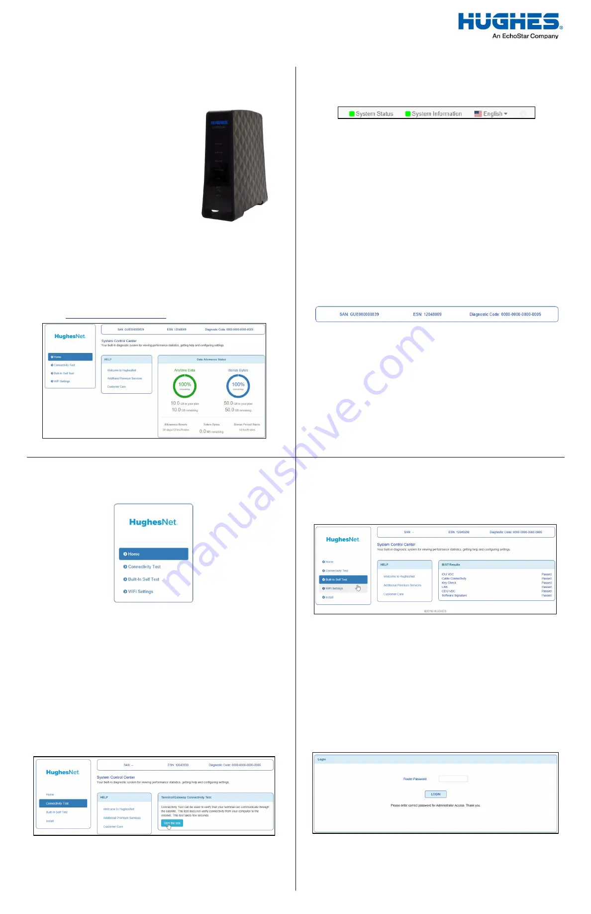
Figure 1: HT2000W satellite modem
System Control Center
The System Control Center is a set of screens and links you can use to
monitor your service and troubleshoot the satellite modem in the event of
a problem. The System Control Center provides access to system status,
configuration information, and online documentation.
To open the System Control Center, follow these steps:
1.
Open a web browser such as Chrome, Firefox, or Internet Explorer.
2.
Type
in the address bar and hit Enter.
Figure 2: System Control Center home page
Indicator links
At the top of each System Control Center page are two indicators (Figure 3)
followed by a link: the System Status link and the System Information link.
Figure 3: Indicators and links
The System Status indicator changes color to indicate the operational
status of the satellite modem.
A
red
indicator means the system has a problem.
An
orange
indicator means the system is in FAP condition.
A
yellow
indicator means the system is operational in a degraded
condition.
A
green
indicator means that all functions are operating within normal
parameters.
Click the
System Status
link to view a detailed report of the functions of the
modem.
Click the
System Information
link to view the unique identifying details of
the modem’s hardware and software.
Parameters bar
The parameters bar (Figure 4) appears at the top of all System Control
Center screens and displays the Site Account Number (SAN), Electronic
Serial Number (ESN), and Diagnostic Code, which is used to troubleshoot
problems when calling Customer Care.
Figure 4: Parameters bar
Center panel links and information
The System Control Center home page center panel includes the following
text links and informational panels once service is activated.
Welcome to HughesNet – Gives you access to the HughesNet Web
Portal, which contains a variety of useful tools, resources, and
information.
Additional Premium Services – Gives you access to additional services
and self-help information
Customer Care – Navigates to the Customer Care page where you
manage the various facets of your account.
Side panel
Figure 5 shows links appearing on the left side of the System Control Center
screen.
Figure 5: Side panel links
The Home link opens the System Control Center home page.
The Connectivity Test link opens the Connectivity Test page, which you
can use to test the connection between the satellite modem and the
NOC.
The Built-In Self Test link checks the internal operation of the modem.
The Wi-Fi Settings link allows you to customize certain aspects of the
modem’s Wi-Fi functionality.
Connectivity Test
Use the Connectivity Test link on the side panel to check the connectivity to
the Hughes Network Operations Center (NOC). To run the test:
1.
Click the
Connectivity Test
link in the side panel. The
Terminal/Gateway Connectivity Test appears in the center of the
screen.
2.
Click the
Start the test
link shown in Figure 6.
Figure 6: Connectivity Test start screen
Built-In Self Test
Use the
Built-In Self Test
link on the side panel to check the connectivity of
the satellite modem.
1.
To initiate the test, click the
Built-In Self Test
link on the side panel.
The test results appear on the page, as shown in Figure 7.
Figure 7: Built-In Self Test results
Note:
If the Built-In Self Test fails, contact Customer Care for assistance.
See the Contact Information section on the back of this page for
details.
Wi-Fi Settings
Use the
Wi-Fi Settings
link to access pages that allow you to manage various
features of the modem’s Wi-Fi service.
1.
To access these pages, click the
Wi-Fi Settings
link on the side
panel. You will see the login page as shown in Figure 8.
2.
The default password is “admin.” Enter this password in the dialog
box and click
Login
.
Figure 8: Wi-Fi Settings login screen
4
3
1
2
* Do not block any of the modem’s
ventilation openings. Leave six inches
around the top and sides of the modem
to ensure adequate ventilation. Do not
put the modem near a heat source such
as direct sunlight, a radiator, or a vent.
* SAT coaxial cable must be connected to
ground block and routed to earth ground
at building entry point.


