5
5 INCH CHIPPER/SHREDDER
ENGLISH
Section
2
ASSEMBLY
2.1 INSTALL THE HOPPER
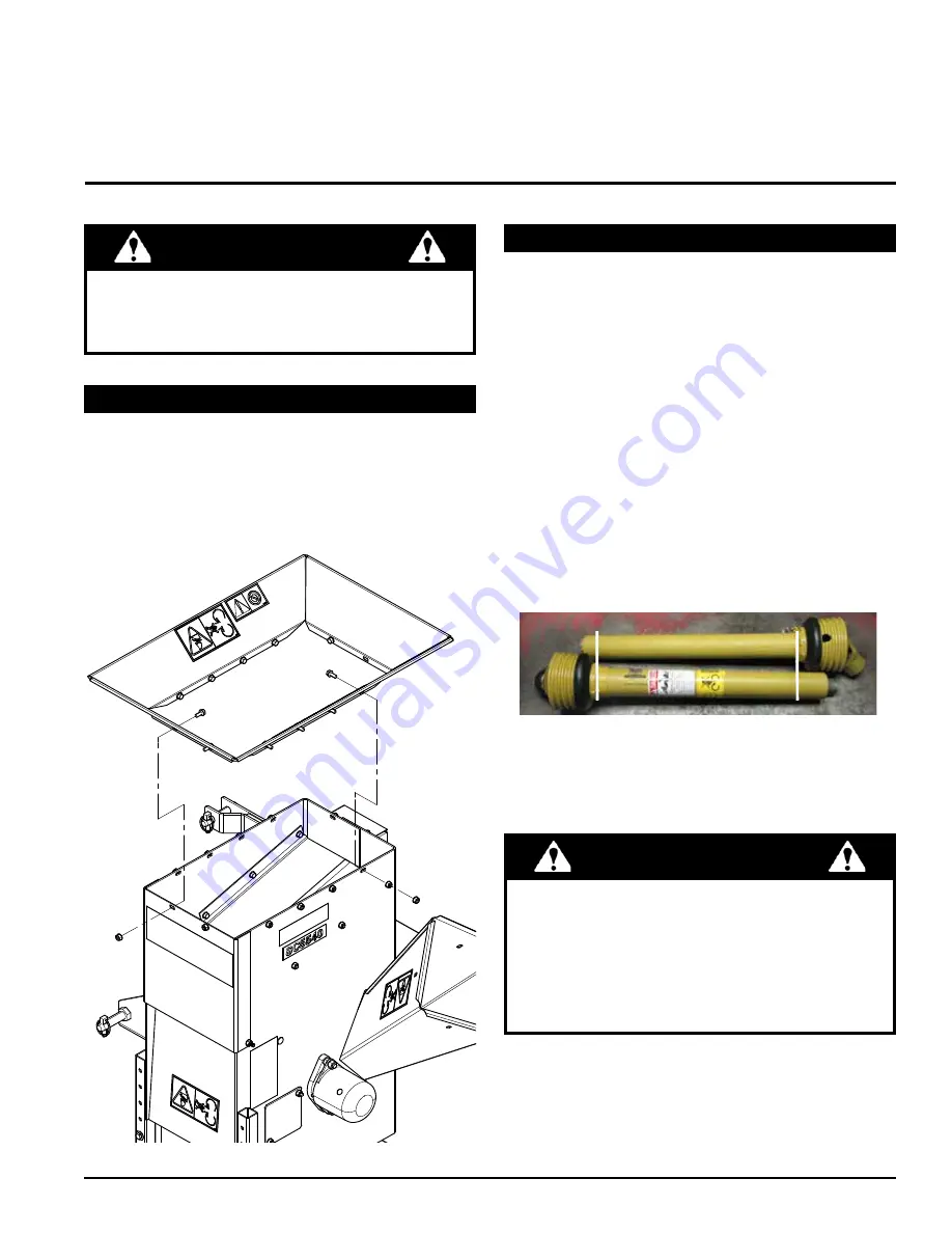
1. Place the hopper assembly on top of the shredder
frame. The tabs on the bottom of the hopper should
be placed inside the shredder frame.
2.
Secure with eleven (11) 5/16" × 3/4" hex bolts and
nylock nuts. Insert the bolts from inside the hopper.
If any bolts or nuts are dropped in the machine, be
sure to remove them before starting the machine.
Remove items from the shredder area by removing the
discharge screen.
WARNING
2.2 CONNECT THE PTO DRIVELINE
The driveline supplied with this machine may need to be
cut to a shorter length for proper operation with the tractor
being used. To determine if driveline will need to be cut,
follow steps below or consult attached driveline manual.
1. BEFORE ATTACHING THE DRIVELINE:
attach the
machine to the tractor with three-point hitch system.
2. Raise and lower machine on three-point hitch to
determine the shortest possible working distance
between the tractor PTO shaft and the drive shaft of
the machine.
3. Pull the driveline apart so the two pieces are
separated. Attach the 6-splined connector for the
outer tube to the tractor, and attach the connector for
the inner tube to the machine.
4. Position installed driveline halves parallel to one
another. (Photo below is example of driveline overlap.)
5.
On larger outer tube, measure back 1‑1/4" (32 mm)
from lower yoke shield and mark plastic tube. Repeat
this process for smaller inner plastic tube measuring
1‑1/4" (32 mm) back from upper yoke shield.
●
The tractor must have a standard 540 RPM PTO
shaft.
●
If the tractor has an electric PTO clutch, consult
your dealer for correct operating procedures.
●
Consult the attached GKN Walterscheid driveline
manual for complete service and maintenance
recommendations.
IMPORTANT


