


M
ODEL
D
ESCRIPTIONS
AND
S
PECIFICATIONS
R
EQUIRED
T
OOLS
3
Model Descriptions and
Specifications
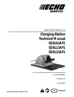
Charging Station
Components
Installation
Requirements
1)
Develop an installation plan and a map of the
site.
2)
Identify the location for installing the AC power
supply, Station Loop peripheral wire(s), and Field
Zone peripheral wire(s).
3)
Install the charging station on flat ground where
flooding or water accumulation will not occur.
4)
Do not bend, warp, or crack the base of the
charging station during installation.
Required Tools
AC Power Supply Wiring
Use 14 AWG electrical wire and ½ in. diameter liq
‐
uid
‐
tight electrical conduit for AC power into the
charging station.
NOTE:
Wire and conduit are not included with the
charging station.
Model
Description
CGSL01AF1
Supports the Station Loop peripheral wire
only.
CGSL11AF1
Supports the Station Loop peripheral wire
and one Field Zone peripheral wire.
CGSL21AF1
Supports the Station Loop peripheral wire
and two Field Zone peripheral wires.
Specifications (all models)
Operating Temperature
32 to 122 °F (0 to 50° C)
Input
120 VAC
‐
60 Hz (360 W
maximum)
Charge Outputs
32 VDC (320 W maximum)
Output Circuits
Class 2
1 – Enclosure top
2 – Debris cover
3 – Charging arm
4 – Enclosure base
5 – Input panel / Serial number location
4
3
2
1
4
3
2
1
5
5
8 mm Deep
‐
well Socket / Driver Tape Measure
3 mm Flat
‐
Blade Screwdriver
Hammer
#1 Phillips Screwdriver
Slip
‐
Joint Pliers
Adjustable Wrench
T
‐
27 Torx® Driver
(included with charging station)
Wire Strippers
1 – Ground (green)
2 – Neutral (white)
3 – Line (black)
4 – Liquid
‐
tight electrical conduit
14 AWG
14 AWG
1
2
3
4


