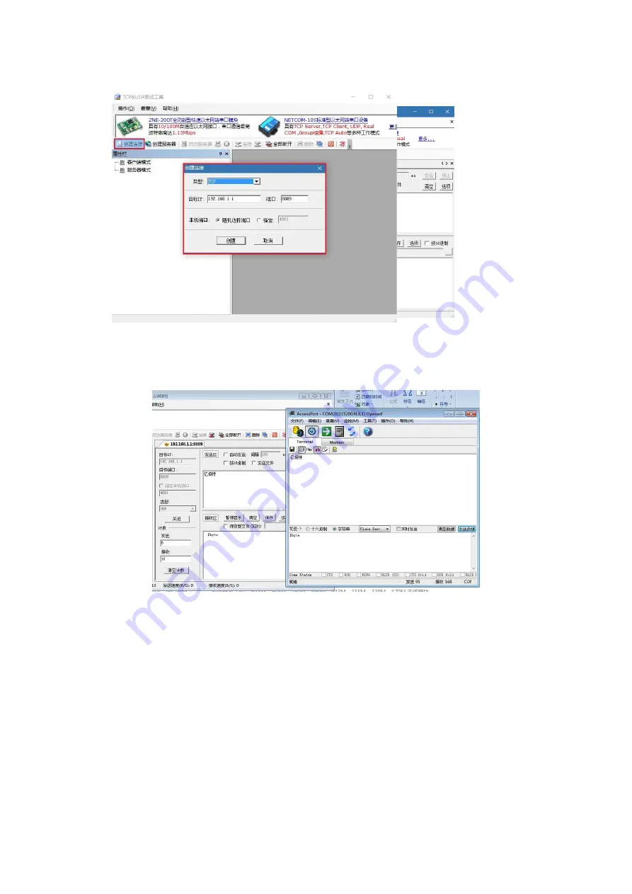
②
. Click the "Create" button to complete the creation, and then click the "Connect" button.
③
. The LED2 of the module base board is always on (GPIO10 is pulled low), which indicates that the connection is
completed, and you can finish the bi-directional data transfer between PC and module (i.e. TCP&UDP test tool and
serial debugging assistant communicate in both directions), otherwise, please operate the above steps again.
④
. You can also transfer files (preferably TXT format files), so try it out.
3.1.3 Module as AP to establish UDP SERVER wireless connection with PC
Let's establish the UDP communication, which requires us to do a simple configuration of the module.
①
. Please make sure the link preparation work is completed successfully.
②
Enter AT command mode for simple configuration. (Please be sure to complete the operation of serial number 1
first, because we are sending commands, please turn off the Real Time Send function of serial port for better debugging,
if you use the serial debugging assistant without the Real Time Send function, please ignore this article)
a. Start serial debugging, enter the command "++++" in the send text box (please do not add line break), click Send to
start sending commands.
b. If the serial port returns "Entered AT mode" message, it indicates that it has entered AT command mode, otherwise,
please operate the above steps again.


