Operating Instructions
10/2011 MN04802012Z-EN
replaces M001485-08, 03/2010
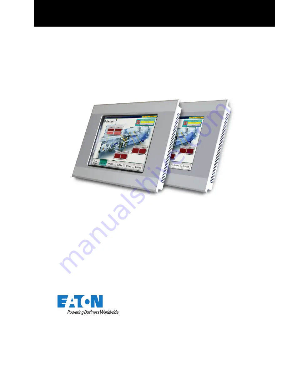
XVS400 10.4"/12.1"/15"MICRO PANEL
Страница 1: ...Operating Instructions 10 2011 MN04802012Z EN replaces M001485 08 03 2010 XVS400 10 4 12 1 15 MICRO PANEL...
Страница 2: ...tion AG CH 9008 St Gallen All rights reserved also for the translation None of this document may be reproduced or processed duplicated or distributed by electronic systems in any form print photocopy...
Страница 3: ...lification of personnel 13 3 3 3 Operating Instructions 13 3 3 4 Installation maintenance and disposal 13 3 3 5 Prohibited use 13 3 3 6 Requirements for proper operation 14 3 4 Device related hazards...
Страница 4: ...2 4 Recalibrating the infra red touch 49 7 2 5 Battery 49 7 3 Service 50 7 3 1 Repairs 50 7 4 Troubleshooting 51 8 Storage transport and disposal 53 8 1 Safety regulations 53 8 2 Storage 53 8 3 Trans...
Страница 5: ...auto mation eaton com 1 3 Additional documentation The following documents may be helpful in the use of the device in addition to this document These can be downloaded from our home page www eaton aut...
Страница 6: ...1 General 1 3 Additional documentation 6 MICRO PANEL XVS400 10 4 12 1 15 10 2011 MN04802012Z EN www eaton com...
Страница 7: ...and system building They are designed exclusively for the visualization operation and control of machines and systems Any other use must be agreed beforehand with the manufacturer 2 4 Device versions...
Страница 8: ...10 4 12 1 depend on the device version 2 5 1 Package contents for devices with resistive touch Tab 2 Package contents for devices with resistive touch Qty Designation 1 MICRO PANEL XVS 430 10MPI or X...
Страница 9: ...VS 440 12MPI MS2 440 10MPI or MS2 440 12MPI 6 Retaining brackets with threaded pin for mounting the device 1 Sealing strip for mounting the device 1 Power supply connector 1 CF slot cover fitted Qty D...
Страница 10: ...ontains the following information Manufacturer address Type designation Power supply required Part no Part No or Art No Serial no Time of manufacturing week year Approval mark and information to the a...
Страница 11: ...he current state of the art and complies with all recognized safety requirements The device must only be installed and commissioned in perfect technical condition and in compliance with this document...
Страница 12: ...word DANGER Indicates an imminently hazardous situation which if not avoided will result in death or serious injury WARNING Signal word WARNING Indicates a potentially hazardous situation which if not...
Страница 13: ...ions It must be ensured that any person working with the device in any phase of its lifespan has read and understood the relevant sections of the Operating Instructions 3 3 4 Installation maintenance...
Страница 14: ...the Operating Instructions and must observe the requirements described The ambient conditions stated must be observed See Chapter 9 9 Ambient conditions 63 The maintenance work must be carried out cor...
Страница 15: ...the device before removing the plug connections WARNING Live parts in the device When the device is opened there is a risk of electric shock if live parts are touched The device must not be opened WA...
Страница 16: ...of write cycles possible on CF cards is limited A power failure during write operations will most likely lead to loss of data Before removing the CF card in CF slot 1 ensure that no software write op...
Страница 17: ...and the lifespan of the device is reduced Protect the device against direct sunlight UV rays CAUTION Cleaning the device Damage to the device due to the use of pointed or sharp objects or by liquids D...
Страница 18: ...3 Safety regulations 3 4 Device related hazards 18 MICRO PANEL XVS400 10 4 12 1 15 10 2011 MN04802012Z EN www eaton com...
Страница 19: ...front Fig 3 Operating and indication elements on the front figure shows device with infra red touch Element Function A Touch sensor Detection of the actuation of the operating elements shown on the di...
Страница 20: ...rating elements on the service side Fig 4 Operating elements on the service side CF slot cover fitted Fig 5 Operating elements on the service side CF slot cover removed Element Function A CF slot cove...
Страница 21: ...ccessed B PROFIBUS ACT green Lit if data is transferred via the Profibus interface C TOUCH ACT green Dark during boot up Lit when the touch sensor is ready Flashes when actuating the touch sensor D TO...
Страница 22: ...4 Operating and indication elements 4 3 Indication elements on the service side 22 MICRO PANEL XVS400 10 4 12 1 15 10 2011 MN04802012Z EN www eaton com...
Страница 23: ...EL XVS400 10 4 12 1 15 10 2011 MN04802012Z EN www eaton com 23 5 Installation 5 1 Safety regulations Read Chapter 3 Safety regulations 11 before installing and commissioning the de vice This contains...
Страница 24: ...end product not required for the front of the device 5 2 2 Requirements for the mounting position The device is designed for mounting in control cabinets control panels or control desks 10 4 and 12 1...
Страница 25: ...el to the cable This should have a cross section that is a multiple of the cable shield CAUTION Operational malfunctions Use of unsuitable or improperly prepared cables as well as incorrect wiring wil...
Страница 26: ...8 Overview of interfaces Fig 7 Connector side of the device Fig 8 Service side of the device Interface Interface description A Power supply Chapter 5 3 3 29 B System Port Chapter 5 3 4 30 C Ethernet C...
Страница 27: ...nector casings with a cable clamp for strain relief The cable clamp must be screwed securely to the connector Connecting the cable shield 1 Strip the cable end so that approx 3 cm of the shield braid...
Страница 28: ...prepared with D Sub connector A Cable with cable sheath B Heat shrinkable tubing or rubber grommet C Cable clamp D Shield braid E D Sub connector F Mounting screw UNC The EMC values stated in the tech...
Страница 29: ...5 3 ST 5 08 connector Phoenix order no 1757022 is supplied with the device Tab 9 Assignment of connector The following must be observed when the connector wiring is prepared Tab 10 Preparing the wiri...
Страница 30: ...12 Relationship of cable length baud rate CAUTION Non isolated interfaces The device may be damaged due to potential differences The GND terminals of all bus stations must be connected Fig 13 RS232 in...
Страница 31: ...erfaces MICRO PANEL XVS400 10 4 12 1 15 10 2011 MN04802012Z EN www eaton com 31 When preparing the cables ensure that there is a low resistance connection between the cable shield and the connector ca...
Страница 32: ...r router Tab 13 Control LEDs of the Ethernet interface Cable Use shielded twisted pair cable STP for networking For device to device connection crossover cable For connecting to the hub switch 1 1 pat...
Страница 33: ...he USB Device interface supports USB 1 1 Cable Only use shielded USB standard cable Maximum cable length 5 m 5 3 7 USB Host The USB Host interfaces support USB 2 0 Cable Only use shielded USB standard...
Страница 34: ...15 Cable specifications Fig 17 Profibus interface 9 pin D Sub female UNC Pin Signal Assignment 1 nc 2 nc 3 B EIA RS 485 line B 4 RTSAS Output for controlling a repeater 5 M5EXT 0V output for external...
Страница 35: ...nd is fed from the bus station It ensures a defined idle signal on the bus when no bus station is transmitting These bus terminations should be implemented externally in the connector casing according...
Страница 36: ...structions for the relevant interface must be observed when wiring the device Any generally applicable regulations and standards must be fulfilled CAUTION Device condensation If the device is or was e...
Страница 37: ...2 1 devices 344 262 mm 1 mm 15 devices 410 315 mm 1 mm Material thickness at the mounting cutout 2 5 mm An additional set of retaining brackets is required for mounting in accordance with IP65 and for...
Страница 38: ...forehand 5 Fit the device from the front into the mounting cutout CAUTION Poor sealing Poor sealing resulting from the twisting of the sealing strip or due to a gap between the ends of the sealing str...
Страница 39: ...cabinet at the fixing points 10 4 and 12 1 devices standard mounting Top and bottom of the device Fit one retaining bracket each at the left and right fixing position CAUTION Mechanical damage to the...
Страница 40: ...and in the center Left and right on the device One retaining bracket each at the central fixing position 15 devices standard mounting Top and bottom of the device One retaining bracket each at the sec...
Страница 41: ...dance with IP65 or used in potentially explosive atmospheres Top and bottom of the device One retaining bracket each at the outermost and at the two innermost fixing positions Left and right on the de...
Страница 42: ...5 Installation 5 4 Mounting 42 MICRO PANEL XVS400 10 4 12 1 15 10 2011 MN04802012Z EN www eaton com...
Страница 43: ...a stylus When wearing gloves ensure that these are clean They must not be covered with abrasive dust or sharp particles CAUTION Device condensation If the device is or was exposed to climatic changes...
Страница 44: ...the CF slot cover Avoid write operations to CF cards Reasons The number of write cycles possible on CF cards is limited A power failure during write operations will most likely lead to loss of data Be...
Страница 45: ...appears while starting booting the device see Chapter 7 4 Troubleshooting 51 4 Complete the following steps after initial commissioning Document MN05010007Z EN System Description Windows CE 4 1 Adjus...
Страница 46: ...operations will most likely lead to loss of data Before removing the CF card in CF slot 1 ensure that no software write opera tions to the CF card are in progress CF ACT LED must not be lit Only remov...
Страница 47: ...MICRO PANEL XVS400 10 4 12 1 15 10 2011 MN04802012Z EN www eaton com 47 7 Maintenance and service 7 1 Safety regulations Read Chapter 3 Safety regulations 11 before working with the device This contai...
Страница 48: ...7 2 1 Cleaning the resistive touch 1 Clean the resistive touch carefully with a clean soft damp cloth With stubborn contamination spray a little cleaning agent onto the damp cloth first 7 2 2 Recalib...
Страница 49: ...red touch Devices with infra red touch do not have to be recalibrated 7 2 5 Battery The integrated battery cannot be exchanged Lifespan see Chapter 9 4 System 59 The infra red touch needs to be cleane...
Страница 50: ...1 MN04802012Z EN www eaton com 7 3 Service 7 3 1 Repairs The device must only be opened by the manufacturer or by an authorized repair center Contact your local supplier or Eaton technical support for...
Страница 51: ...in the CF slot 0 50 Touch is dirty or defect only appears if GALILEO is installed Resistive touch is not correctly calibrated Start boot the device Calibrate touch Document MN05010007Z EN System Desc...
Страница 52: ...tly lit and or the icon appears in the taskbar Incorrect operation of the operating elements on the display Remove all objects from the area of the display Infra red frame of the infra red touch is co...
Страница 53: ...See Chapter 9 9 Ambient conditions 63 8 3 Transport Damage to the device must be prevented during transport use an appropriate packaging The ambient conditions must be fulfilled even when the device i...
Страница 54: ...to the lithium battery soldered in the device and a risk of poisoning due to the mercury content of the cold cathode tubes Dispose of the device properly Component Material Housing Galvanized sheet st...
Страница 55: ...1 10 4 devices Tab 20 Dimensions and weights of the 10 4 devices Fig 30 Mechanical dimensions of the 10 4 devices in mm Property XVS400 10 4 MS2 10 4 Height 260 mm Width 345 mm Depth 67 mm Thickness...
Страница 56: ...Dimensions and weights of the 12 1 devices Fig 31 Mechanical dimensions of the 12 1 devices in mm Property XVS400 12 1 MS2 12 1 Height 279 mm Width 361 mm Depth 67 mm Thickness of front plate 5 mm Mo...
Страница 57: ...22 Dimensions and weights of the 15 devices Fig 32 Mechanical dimensions of the 15 devices in mm Property XVS400 15 Height 332 mm Width 427 mm Depth 73 mm Thickness of front plate 5 mm Mounting depth...
Страница 58: ...8 mm 10 4 screen diagonal 12 1 devices 246 mm 185 mm 12 1 screen diagonal 15 devices 304 mm 228 mm 15 screen diagonal Color resolution Adjustable 65536 or 256 colors Contrast ratio Normally 350 1 Brig...
Страница 59: ...e Property XVS400 10 4 12 1 15 MS2 10 4 12 1 Type Infra red touch Resolution 10 4 devices 79 59 logic channels 12 1 devices 95 71 logic channels 15 devices 107 83 logic channels Property XVS400 10 4 1...
Страница 60: ...ly isolated max 1 5 Mbit s Power supply Chapter 9 5 1 60 DIAG Only for service tasks Property XVS400 10 4 12 1 15 MS2 10 4 12 1 Rated voltage 24 VDC SELV safety extra low voltage Permissible voltage R...
Страница 61: ...24 VDC 15 devices Max 1 5 A 24 VDC Starting current inrush 2 5 A2 s Protection against reverse polarity Yes Fuse Yes replacement only by the manufacturer or by an authorized repair center Potential i...
Страница 62: ...logic controllers equipment require ments and tests Explosion protection in relation to CE ATEX 94 9 EC Zone 22 Category 3D II 3D Ex tc IIIC T70 C IP6x IEC EN 60079 0 Explosive atmospheres equipment g...
Страница 63: ...Property XVS400 10 4 12 1 15 MS2 10 4 12 1 Temperature Operation 0 50 C Storage Transport 20 60 C Relative air humidity 10 95 non condensing Vibration in accordance with IEC EN 60068 2 6 Displacement...
Страница 64: ...9 Technical data 9 9 Ambient conditions 64 MICRO PANEL XVS400 10 4 12 1 15 10 2011 MN04802012Z EN www eaton com...