Eaton SFX Product Family Installation and Operation Manual
SFX Product Line
Страница 1: ...Eaton SFX Product Family Installation and Operation Manual SFX Product Line ...
Страница 2: ...ARTICULAR PURPOSE OR MERCHANTABILITY OTHER THAN THOSE SPECIFICALLY SET OUT IN ANY EXISTING CONTRACT BETWEEN THE PARTIES ANY SUCH CONTRACT STATES THE ENTIRE OBLIGATION OF EATON THE CONTENTS OF THIS DOCUMENT SHALL NOT BECOME PART OF OR MODIFY ANY CONTRACT BETWEEN THE PARTIES In no event will Eaton be responsible to the purchaser or user in contract in tort including negligence strict liability or ot...
Страница 3: ...e our specifications and designs at any time A limited warranty is given with these Eaton products Please see our website for details http www eaton com Eaton ProductsServices Hydraulics WarrantyTermsConditions PCT_612027 Safety Considerations Definitions and Symbols WARNING CAUTION This symbol is the Safety Alert Symbol It occurs with either of two signal words CAUTION or WARNING as described bel...
Страница 4: ...ATION 9 6 0 HARDWARE DESCRIPTION 9 7 0 SOFTWARE DESCRIPTION 12 8 0 SERVICE TOOL INSTALLATION AND GETTING STARTED 12 9 0 FIRMWARE 12 9 1 Install The Firmware 12 10 0 INSTALLING THE CONTROLLER 12 10 1 Mounting Considerations 12 10 2 Product Dimensions 13 11 0 WIRING THE CONTROLLER 13 11 1 Recommended Wiring Practices 13 11 2 Wiring Pin Out 15 11 3 Block Diagram 16 12 0 TESTING VALIDATION 18 13 0 DEV...
Страница 5: ...EATON SFX Product Family Installation and Operation Manual 6045988 001 Rev A E ELCL II005 E March 2019 5 THIS PAGE INTENTIONALLY LEFT BLANK ...
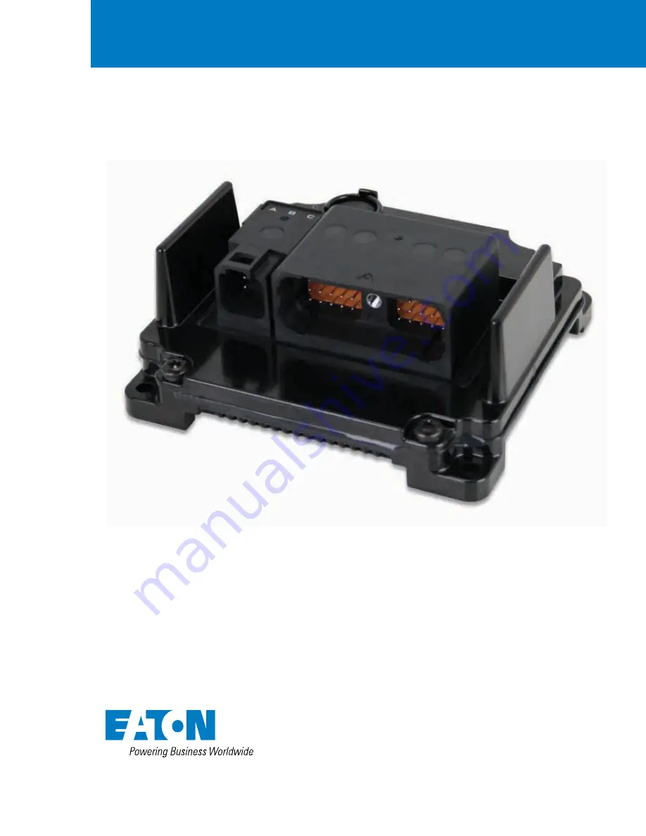
Страница 6: ...e operation in severe environments possessing IP and temperature ratings that exceed existing solutions from competitors SFX controllers employ several advanced technologies e g I O with variable configuration architecture dual processor architecture enabling simple management and enhancing both ease of use and functionality These controllers are intended as both a standalone solution or as the ce...
Страница 7: ...Bit Width 32 Bit FPU Integrated on chip Safety CPU Flash ROM program data combined 2 Mbyte Safety CPU SRAM 128 Kbyte CAN Specification 2 0A 2 0B Baud Rates 50 kb s 100 kb s 125 kb s 250 kb s 500 kb s 800 kb s 1Mb s Protocol SAE J1939 Default Node Address 0 main processor 2 safety processor Default Baud Rate 250kb s Number of Sensor Supplies 1 Sensor Supply Output Voltage 5 VDC or 10 VDC configurab...
Страница 8: ...figurable Dither Amplitude Configurable Control Range 0 05 2 A Control Resolution 1 mA Fly Back Protection Integrated Duty Cycle Resolution 01 250 Hz Output Type PWM High Side Software configurable Max Amperage 4A Diagnostics Open Short circuit protection PWM Frequency 50 500 Hz Dither Frequency Configurable Dither Amplitude Configurable Control Range 0 05 4 A Control Resolution 1 5 mA Fly Back Pr...
Страница 9: ...ing and installation manual should be used in conjunction with other SFX manuals in references Together this information should form a basis for the simple configuration of the controller and the creation of programs specific to your application needs Proper operation of the controller is dependent on the program that is created and ultimately downloaded to the hardware therefore extensive testing...
Страница 10: ...A channels 4 2 Number of channels supporting function PWM 4 2 High Side output 4 2 Low Side output 4 2 H Bridge pair 2 1 SFX20m SFX12m Controller Model 10 I O 6 I O Total Outputs 10 6 Total frequency channels 4 2 Number of channels supporting function High frequency 4 2 Variable reluctance 2 2 Pull up resistor 4 2 Pull down resistor 4 2 Total analog channels 6 4 Number of channels supporting funct...
Страница 11: ...0 inputs can be configured to add either an internal pull up or pull down resistor The SFX12m incorporates 6 total outputs comprised of 2 x 4 A channels 4 x 2 A channels Each channel is capable of High Side output Open loop PWM Closed loop PWM with current control The 2 x 4 A channels are also capable of Low Side output and can be configured as a pair for H Bridge operation The SFX12m also incorpo...
Страница 12: ...tallation process If the wrong firmware has been selected the software will provide a prompt which indicates that the firmware does not match the controller hardware If this occurs verify that the correct firmware was selected The software should then load on the controller and complete installation You should now be ready to proceed with the application software installation 10 0 INSTALLING THE C...
Страница 13: ...reasonable levels under maximum continuous load conditions e g 1 volt on 12 volt systems and 2 volts on 24 volt systems Verify that the harness is constructed to meet the needs of the application environment e g shock vibration moisture temperature chemicals and impact Make certain that the harness is designed and constructed to minimize induced interference resulting from EMI coupling between sig...
Страница 14: ... the controller connector or damage to the wiring harness and is not covered by warranty Prior to Welding In order to avoid damaging the SFX controller ensure that all electrical connectors are fully disconnected from the SFX controller prior to welding on the machine Prior to Electrostatic Painting In order to avoid damaging the SFX controller ensure that all electrical connectors are fully disco...
Страница 15: ...utilize the following pins 8 15 17 25 27 31 32 and 40 1 21 11 31 2 22 12 32 3 23 13 33 4 24 14 34 5 25 15 35 6 26 16 36 7 27 17 37 8 28 18 38 9 29 19 39 10 30 20 40 KEY A Similiar to DRC23 40PA Mating Connector DRC26 40SA J1A E2486101 CA N1 CA N1 CA N2 CA N2 CA N3 CA N3 FREQ1_POS FREQ1_NE G FREQ2_POS FREQ2_NE G FREQ3 FREQ4 INPUT_1 INPUT_2 INPUT_3 INPUT_4 INPUT_5 INPUT_6 PWM1_2A PWM2_2A PWM3_2A PWM...
Страница 16: ...PWM Digital Outputs 2A Current Feedback Digital High Side PWM Digital Outputs 4A Current Feedback Digital High Low Side Sensor Power Supply 1 Note Only FREQ1 FREQ2 support variable reluctance type sensors inputs SENS_PWR 30A SENS_PWR 20A 22A CAN1_H 12A CAN1_L 4P CAN1_H 5P CAN1_L 13A CAN2_H 23A CAN2_L 14A CAN3_H 24A CAN3_L 1P GND 21A INPUT_1 11A INPUT_2 33A INPUT_3 34A INPUT_4 36A FREQ1_POS 37A FRE...
Страница 17: ...ide PWM Digital Outputs 4A Current Feedback Digital High Low Side Sensor Power Supply 1 Note Only FREQ1 FREQ2 support variable reluctance type sensors inputs SENS_PWR 30A SENS_PWR 20A 22A CAN1_H 12A CAN1_L 4P CAN1_H 5P CAN1_L 13A CAN2_H 23A CAN2_L 14A CAN3_H 24A CAN3_L 1P GND 26A Sleep 16A IGN 6A VBATT PWM1_4A 1A PWM2_4A 35A PWM3_4A 31A PWM4_4A 8A 10A Load_PWR 19A Load_PWR 9A Load_PWR Load_PWR 28A...
Страница 18: ... Environmental Storage Temperature Range 40 C 125 C Operating Temperature Range 40 C 105 C Initial Conditioning 40 C for 24 hours 105 C for 24 hours High Temperature endurance 125 C for 200 hours unpowered After test unit must be functional Voltage Range 6 V 32 V Ignition Cycling 10 000 cycles of I minute max supply volt age alternating with 1 minute no voltage at power supply connection Thermal S...
Страница 19: ...n two 120Ω terminating resistors are likely present on the CANbus Find and remove one terminating resistor b If resistance 70Ω is measured only one 120Ω terminating resistor is likely present on the CAN network Add a second terminating resistor in an appropriate location Note CAN1 on the SFX has a switchable internal 120Ω terminating resistor If this is being used CAN1 should measure 120Ω when pro...
Страница 20: ...eserved Printed in USA 6045988 001 Rev A Document No E ELCL II005 E March 2019 Eaton Hydraulics Group Europe Route de la Longeraie 7 1110 Morges Switzerland Tel 41 0 21 811 4600 Fax 41 0 21 811 4601 Eaton Hydraulics Group Asia Pacific Eaton Building No 7 Lane 280 Linhong Road Changning District Shanghai 200335 China Tel 86 21 5200 0099 Fax 86 21 2230 7240 ...