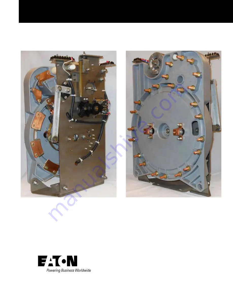
QD5 Quik-Drive voltage regulator tap-changer manual
COOPER POWER
SERIES
Voltage Regulators
MN225012EN
Effective March 2016Supersedes S225-12-
2
February
201
3
Страница 1: ...QD5 Quik Drive voltage regulator tap changer manual COOPER POWER SERIES Voltage Regulators MN225012EN Effective March 2016 Supersedes S225 12 2 February 2013...
Страница 2: ...SS FOR A PARTICULAR PURPOSE OR MERCHANTABILITY OTHER THAN THOSE SPECIFICALLY SET OUT IN ANY EXISTING CONTRACT BETWEEN THE PARTIES ANY SUCH CONTRACT STATES THE ENTIRE OBLIGATION OF EATON THE CONTENTS O...
Страница 3: ...erating sequence 4 MAINTENANCE SERVICE AND TROUBLESHOOTING 5 QD5 TAP CHANGER SCHEMATIC 10 QD5 TAP CHANGER TORQUE REGUIREMENTS 13 QD5 TAP CHANGER REVERSING MOVABLE CONTACT ASSEMBLY KIT 5740785B72ER 19...
Страница 4: ...orking around high voltage lines and equipment and support our Safety For Life mission Safety information DANGER Hazardous voltage Contact with hazardous voltage will cause death or severe personal in...
Страница 5: ...o safety which are common to all regulators This safety hazard information is offered for guidance when installing and operating the descriptive matter to aid in preventing damage to the equipment and...
Страница 6: ...hich will affect the operation of the tap changer Special fixtures are used to assemble the holding switch assembly to ensure that alignment gap setting requirements are met Motor capacitor The QD5 ta...
Страница 7: ...stationary contact at all times The main stationary contacts bolt to collector rings The collector rings insert between a set of button contacts that are able to hold a continuous current path throug...
Страница 8: ...are use to provide a safety switch circuit to prevent the tap changer from tapping beyond 16R and 16L acting as a fail safe to the mechanical stop The switches enable the tap changer to step back fro...
Страница 9: ...ator Figure 10 Tap changer front view Control Winding Terminal Board Holding Switch Assembly Drive Pinion Cam Main Stationary Contact Safety Switches PI Drive Face Geneva Gear Brake Assembly Main Term...
Страница 10: ...ionary 2 Stationary 1 Main Stationary Contact VL Reversing Stationary Contact Neutral Stationary VR Reversing Stationary Contact 8 Stationary 4 Stationary Reversing Neutral Stationary Contact 6 QD5 QU...
Страница 11: ...r Brake Assembly Raise Safety Switch Neutral Switch Lower Safety Switch Reversing Segment Actuator Drive Sprocket Gear Logic Switches Chain 7 QD5 QUIK DRIVE TAP CHANGER INSTALLATION AND MAINTENANCE IN...
Страница 12: ...rive frame with Geneva gear Geneva Gear Reversing Segment Actuator Movable Contact Actuator Finger Drive Sprocket Gear 8 QD5 QUIK DRIVE TAP CHANGER INSTALLATION AND MAINTENANCE INSTRUCTIONS MN225012EN...
Страница 13: ...Contact Main Movable Contacts Main Stationary Contact 1 Movable Contact Insulator Arm VR Stationary Contact Neutral Main Stationary Contact Main Stationary Contact 8 Inner Collector Ring Outer Collec...
Страница 14: ...QD5 tap changer schematic Figure 15 QD5 wiring schematic 10 QD5 QUIK DRIVE TAP CHANGER INSTALLATION AND MAINTENANCE INSTRUCTIONS MN225012EN March 2016...
Страница 15: ...l produce the typical erosion patterns above INTERMEDIATE STAGE STATIONARY CONTACT STATIONARY CONTACT EROSION EROSION NEW CONTACTS ARCING INSERT ARCING INSERT EROSION HAS PROGRESSED TO A POINT WHERE B...
Страница 16: ...shown in Figures 21 and 22 must definitely be replaced The figures below show actual contacts after various stages of contact erosion New contacts Figure 17 QD5 tap changer movable contact Figure 18 Q...
Страница 17: ...ure 24 Front drive torque requirements 30 40 in lbs 3 4 4 5 Nm 4 5 in lbs 0 5 0 6 Nm 180 192 in lbs 20 3 21 6 Nm 12 18 in lbs 1 4 2 0 Nm Stationary Contact Reversing Stationary Contact 80 90 in lbs 9...
Страница 18: ...e 26 Motor pivot stud and locknut torque requirements 18 20 lb in 5 2 2 Nm 180 192 lb in 20 2 21 6 Nm Figure 27 Geneva gear torque requirements 65 75 in lbs 7 5 8 5 Nm 14 QD5 QUIK DRIVE TAP CHANGER IN...
Страница 19: ...e tap changer Parts supplied Item Part Number Description Qty 1 0740785B72 Reversing Movable Contact 1 Tools required Ratchet Wrench 3 8 inch Socket 7 16 inch Socket 9 16 inch Deep well Socket 1 4 inc...
Страница 20: ...7 16 wrench loosen and remove both bushing mounting bolts See Figure 32 4 Remove the bushing from the reversing movable contact shaft See Figure 32 Figure 31 Bushing Figure 30 Removal of actuator arm...
Страница 21: ...Use a 9 16 wrench to loosen and remove the nuts and flat washers from both of the reversing neutral stationary contacts on the back of the tap changer contact panel See Figure 36 Figure 34 Removal of...
Страница 22: ...actuator shaft into the new reversing movable contact assembly See Figure 39 13 Place the reversing movable contact into the mounting slot in the tap changer front panel aligning the movable contact...
Страница 23: ...act panel Align the movable contact assembly so that the reversing movable tube aligns with and goes through the hole in the contact panel At this point the stationary contact and movable contact shou...
Страница 24: ...ent arm onto the reversing actuator shaft Align the square portion of the shaft with the square hole in the arm If needed place a screwdriver through the movable contact tube and push the shaft forwar...
Страница 25: ...Figure 51 Figure 50 Neutral stationary contact position for main movable contacts Figure 51 Neutral position for reversing movable Reversing Movable Contact Reversing Neutral Stationary Contact 21 Pla...
Страница 26: ...e holding switch actuator See Figure 52 Figure 52 Neutral position for position indicator pinion cam and holding switch Pinion Cam Holding Switch Actuator 22 QD5 QUIK DRIVE TAP CHANGER INSTALLATION AN...
Страница 27: ...tion procedure Removing existing contact assembly Note N Retain all hardware 1 Hold the reversing movable contact assembly to prevent it from moving Using a 9 16 wrench loosen and remove the reversing...
Страница 28: ...mounting screws See Figures 58 and 59 Figure 57 Removing reversing movable contact bushing Bushing Reversing Movable Contact Tap Changer Plate Figure 58 Logic switch removal Reversing Logic Switch Mo...
Страница 29: ...ovable contact assemble disengages from the reversing neutral stationary contact and remove it from the tap changer See Figure 63 10 Remove the reversing neutral stationary contact assembly from the t...
Страница 30: ...able contact assembly until the middle button contact is fully engaged in the center of the reversing stationary contact blade See Figure 66 4 Slide the stationary and movable contact assembly toward...
Страница 31: ...reversing segment arm onto the reversing actuator shaft Align the square portion of the shaft with the square hole in the arm If needed place a screwdriver through the movable contact tube and push th...
Страница 32: ...her components are aligned in the neutral position 2 Confirm that the regulator is in the neutral position A Main movable contacts are located on the neutral stationary contact which is located at the...
Страница 33: ...ding switch actuator See Figure 76 Figure 75 Neutral position for reversing movable Reversing Movable Contact Reversing Neutral Stationary Contact Figure 76 Neutral position for position indicator pin...
Страница 34: ...to Service Information MN225026EN General The purpose of this replacement kit is to provide the parts and installation instructions for replacing the main stationary contacts on a QD5 Quik Drive tap...
Страница 35: ...o be replaced 7 When the movable contacts are located on the stationary contact to be replaced the movable contacts must be moved Place a 3 8 socket onto the rear shaft of the motor See Figure 82 Usin...
Страница 36: ...neutral position A Main movable contacts are located on the neutral stationary contact which is located at the 11 o clock position and under the reversing switch movable contact assembly See Figure 83...
Страница 37: ...y contact assembly kit number 5791646A25 Refer to Service Information MN225027EN General The purpose of this replacement kit is to provide the parts and installation instructions for replacement of th...
Страница 38: ...ered edge is facing in the wrong direction the stationary VR contact is being used See Figure 90 6 Place a flat washer and nut on each stud Use a 9 16 socket and ratchet to tighten the nuts on each co...
Страница 39: ...the neutral position A Main movable contacts are located on the neutral stationary contact which is located at the 11 o clock position and under the reversing switch movable contact assembly See Figur...
Страница 40: ...contact will begin to move QD5 tap changer VR reversing stationary contact assembly kit number 5791646A27 Refer to Service Information MN225028EN General The purpose of this replacement kit is to pro...
Страница 41: ...stationary contact If the tapered edge is facing in the wrong direction the stationary VL contact is being used See Figure 99 6 Place a flat washer and nut on each stud Use a 9 16 socket and ratchet t...
Страница 42: ...embly See Figure 101 B The reversing movable contact is located on the reversing neutral stationary contact See Figure 102 Figure 101 Neutral stationary contact Neutral Stationary Contact Main Movable...
Страница 43: ...ench 1 4 inch Socket 3 8 inch Socket Phillips Head Screwdriver 2 Standard Blade Screwdriver Diagonal Cutters Loctite 243 Threadlocker External Snap Ring Pliers 0 200 in lbs 0 25 Nm Torque Wrench Crimp...
Страница 44: ...shown in Figure 109 remove the motor pivot stud lock nut with a 9 16 socket on a ratchet Pull the motor off of the motor pivot stud make sure the Belleville washer stays on the motor pivot stud and d...
Страница 45: ...nd sprocket Refer to Figure 112 Remove the motor from the tap changer assembly 9 Remove the four screws securing the motor to the motor mounting plate using a 1 4 socket on a ratchet Remove the motor...
Страница 46: ...e motor replacement kit Do not fully tighten Make sure the motor wires are extending out of the top right of the motor when looking at the motor from the sprocket end Refer to Figure 116 Using a torqu...
Страница 47: ...nting hole in the motor mounting plate Secure the motor mounting plate to the motor pivot stud with the locknut removed in Step 6 Refer to Figures 118 and 119 Using a torque wrench with a 9 16 socket...
Страница 48: ...he end of each wire Crimp a supplied ring tongue connector to the end of each wire making sure the wire is fully inserted into the ring tongue connector The wire should not stick out of the connector...
Страница 49: ...act which is located at the 11 o clock position and under the reversing switch movable contact assembly See Figure 125 B The reversing movable contact is located on the reversing neutral stationary co...
Страница 50: ...rocedure 1 The tap changer should be secured to a bench before starting the replacement procedure if the tap changer has been removed from the unit 2 The tap changer should be in the neutral position...
Страница 51: ...ft in place during this procedure Refer to Figures 133 and 134 7 Push the main shaft from the threaded end partially through the steel front plate of the tap changer so that the retaining ring on the...
Страница 52: ...back of the molded panel Pull the contact rings out of the button contacts and remove the movable contact panel assembly Refer to Figure 138 11 Remove the three button head screws nuts and washers th...
Страница 53: ...between the contact ring and the movable contact panel and align the holes Insert the three button head screws from the contact ring side of the assembly so the screw heads secure the contact ring in...
Страница 54: ...ion it against the movable contact panel Refer to Figure 146 18 Line up the main shaft with the hole in the Geneva gear Push the shaft through Geneva gear until the threaded end of the shaft reaches t...
Страница 55: ...aft the remainder of the way through the hole in the steel plate Secure the steel shaft to the steel panel using the 1 2 13 lock nut Use a 5 8 open end wrench to hold the steel shaft while securing th...
Страница 56: ...locker to the two actuator finger bolts and then install the actuator finger It may be necessary to reposition the movable contact insulator arm if the holes do not quite line up See Figure 152 25 Pla...
Страница 57: ...holding switch actuator See Figure 155 Figure 155 Neutral position for position indicator pinion cam and holding switch Pinion Cam Holding Switch Actuator 53 QD5 QUIK DRIVE TAP CHANGER INSTALLATION A...
Страница 58: ...This page is intentionally left blank 54 QD5 QUIK DRIVE TAP CHANGER INSTALLATION AND MAINTENANCE INSTRUCTIONS MN225012EN March 2016...
Страница 59: ...This page is intentionally left blank 55 QD5 QUIK DRIVE TAP CHANGER INSTALLATION AND MAINTENANCE INSTRUCTIONS MN225012EN March 2016...
Страница 60: ...I 53188 Eaton com cooperpowerseries 2016 Eaton All Rights Reserved Printed in USA Publication No MN2225012EN March 2016 SAFETY FOR LIFE Eaton is a registered trademark All trademarks are property of t...