4 Accessories
4.7 Device-specific accessories for devices with an IP20 degree of protection
DC1-S…20…, DC1-S…OE1 Variable Frequency Drives
05/21 MN040058EN
www.eaton.com
97
4.7.1 DXC-EXT-IO… coupling module
Coupling modules DXC-EXT-IO110 and DXC-EXT-IO230 can be used to
integrate the digital inputs on DC1-S… variable frequency drives directly into
control circuits with 110 V AC / 230 V AC. In the actual coupling module, the
inputs (connection terminals 1 to 4 and 12 and 13) are galvanically isolated
from the DC1-S… variable frequency drive’s digital inputs (DI1 to DI4).
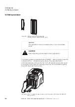
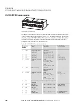
Figure 66: DXC-EXT-IO110 and DXC-EXT-IO230
Table 22: DXC-EXT-IO… connection terminals
→
For more information on the coupling modules and on output
expansions, please refer to Application Note AP040032
(DC1, I/O Configuration).
Connection
terminal
Signal
Description
Default Setting
1
N
Reference point for digital inputs DI1, DI2, DI3
–
2
DI1
Digital Input 1
DXC-EXT-IO110:
100 V - 10 % - 120 V + 10 %
DXC-EXT-IO230:
200 V - 10 % - 240 V + 10 %
FWD
3
DI2
Digital input 2
DXC-EXT-IO110:
100 V - 10 % - 120 V + 10 %
DXC-EXT-IO230:
200 V - 10 % - 240 V + 10 %
Select Quick-dec
4
DI3
Digital Input 3
DXC-EXT-IO110:
100 V - 10 % - 120 V + 10 %
DXC-EXT-IO230:
200 V - 10 % - 240 V + 10 %
Select AI1REF/f-Fix1
5
+10 V
Reference voltage
10 mA max.
Reference potential: 0 V
(terminals 7 and 9)
–
6
AI1
Analog Input 1
1)
0 - 10 V, R
i
> 72 k
Ω
0/4 - 20 mA, R
B
= 500
Ω
AI1 REF
(analog, 0 - 10 V)
7
0 V
Common reference potential for all digital and analog inputs
and outputs together with terminal 9
–
1 2 3 4 5 6 7
8 9 10 11
Содержание PowerXL
Страница 4: ......
Страница 124: ...5 Operation 5 7 Handling the keypad 120 DC1 S 20 DC1 S OE1 Variable Frequency Drives 05 21 MN040058EN www eaton com...
Страница 160: ...6 Parameter structure 6 7 Fault messages 156 DC1 S 20 DC1 S OE1 Variable Frequency Drives 05 21 MN040058EN www eaton com...
Страница 170: ...7 Technical Data 7 3 Dimensions 166 DC1 S 20 DC1 S OE1 Variable Frequency Drives 05 21 MN040058EN www eaton com...


