3 Installation
3.6 Electrical Installation
98
DC1…20… and DC1…OE1 Variable Frequency Drives
02/20 MN040059EN
www.eaton.com
3.6.2.5 Digital Output (Transistor)
When using the device’s default configuration, control signal terminal 8 will
be configured as an analog output (AO).
It can be set to work as a digital output instead (DO) with parameter P-25:
Table 13: Control signal terminal 8 (DO)
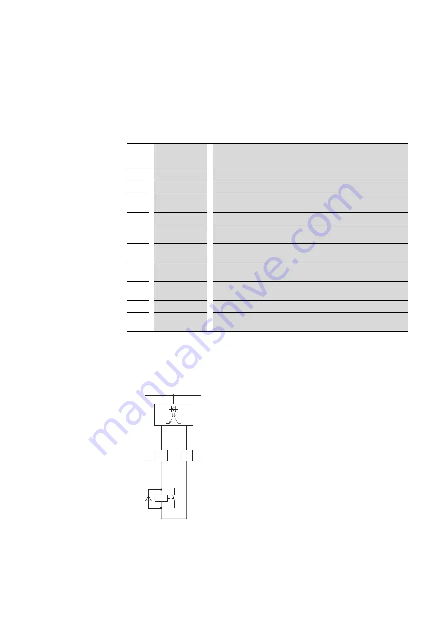
Transistor output DO uses control signal terminal 8 to switch the device’s
internal control voltage (+24 V) as a digital signal (1 = High). The maximum
permissible load current is 20 mA.
Figure 56:
Connecting example (interposing relay with free-wheel diode ETS4-VS3)
P-25
Signal
1 = High (+24 V)
Description
0
RUN
Enable (FWD/REV)
1
Ready
Ready for operation. No fault signal
2
Actual value =
Setpoint value
The output frequency (f-Out) or speed is equal to the setpoint value (REF).
3
Error (Fault)
Fault (not ready).
4
f-Out
≧
P-19
The output frequency (f-Out) is greater than or equal to the value set in P-19
(RO1 upper limit).
5
I-Out
≧
P-19
The output current (I-Out) is greater than or equal to the value set in P-19 (RO1
upper limit).
6
f-Out < P-19
The output frequency (f-Out) is less than the value set in P-19 (RO1 upper limit).
7
I-Out < P-19
The output current (I-Out) is less than the value set in P-19 (RO1 upper limit).
10
Not Enable
No enable signal (FWD/REV)
11
Actual value
≠
Setpoint value
The output frequency (f-Out) / speed is not equal to the setpoint value (REF).
Digital output DO: Accuracy
≧
1% relative to maximum value
→
Control terminals 7 and 9 are the common 0 V reference
potential for all analog and digital input signals.
< 20 mA
DO
OV
8
9
+
+ 24 V


