


UPS SYSTEM INSTALLATION
Eaton Power Xpert 9395P-1200 UPS (1200 kVA, 1200 kW) Installation and Operation Manual
S
P-164000500 Rev 4
www.eaton.com/powerquality
4-21
8.
If wiring a distributed bypass system, proceed to Step 9; otherwise, proceed to
Step 11.
9.
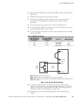
Using hardware from the external wiring terminal hardware kit (see Table 3‐18),
connect phase A, B, and C wiring from the output terminals of each UPS unit to
the customer-supplied tie cabinet or load distribution panel. See paragraph 3.2.3
for wiring and termination requirements.
10.
11.
Using hardware from the external wiring terminal hardware kit (see Table 3‐18),
connect phase A, B, and C power wiring from output terminals to the critical
load. See paragraph 3.2.3 for wiring and termination requirements.
12.
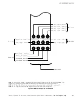
NOTE
AC Input to Bypass terminals are not applicable to an IOM configuration.
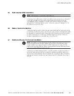
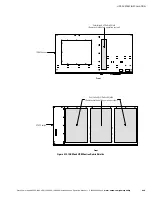
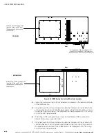
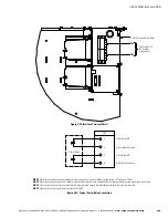
(See Figure 4‐18 for Detail AA.)
DC Input from B (E4)
For 4-wire systems only
DC Input from Battery - (E5)
AC Input to UPS Rectifier
(A, B, C)
AC Input to UPS Bypass
(A, B, C)
(See Figure 4‐18 for Detail AA.)
ISBM
(See Figure 4‐19 or
Figure 4‐20 for Detail BB.)
(See Figure 4‐19 or Figure 4‐20
for Detail BB.)
AC Output
to
Critical Load
Phase C (E11)
Phase A (E9)
Phase B (E10)
A
B
C
N
(E12)
Neutral
For 4-wire
systems
only
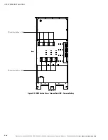
Figure 4‐17. ISBM Section Power Terminal Locations
Содержание Power Xpert 9395P-1200
Страница 195: ......
Страница 196: ... P 1640005004 P 164000500 4 ...