Eaton MENVIER30 Скачать руководство пользователя страница 5

Menvier30 

Page 1 

1. Introduction 

The Menvier30 is a control unit for a hybrid 
wired/radio alarm system intended for commercial 
or large domestic use.  

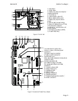
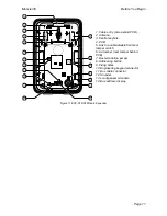
The control unit comprises a steel case containing 
the control unit PCB (printed circuit board), power 
supply and space for a 17Ah backup battery. 

The control unit PCB provides terminals for a 
single bus. The bus allows you to connect up to 
10 bus devices using standard four wire alarm 
cable. The bus devices can be any mixture of 
keypads, zone expanders (for wireless or wired 
detectors) or remote power supplies. 

The control unit PCB also provides a range of 
connectors for outputs, communicators, and up to 
10 Fully Supervised Loop (FSL), or 10 two-wire 
Closed Circuit Loop (CCL) or five four-wire CCL 
zones. 

The Menvier30 at release 4 uses keypads with 
software revision 3.02 and above. The keypads 
allow end users to set and unset the system, and 
the installer to configure the control unit.  

Note that to work correctly the Menvier30 must be 
fitted with at least one wired keypad. 

The following types of keypad available for 
connection to the Menvier30: 

i-kp01 

This keypad contains an integral 
proximity tag reader, allowing end 
users to control the system without 
having to remember access codes. 

KEY-K01 

This keypad has no internal prox 
reader, and is supplied in a square 
format case. 

KEY-KP01 

This product, supplied in the same 
case as the KEY-K01, has an 
internal prox reader and also 
provides terminals for an external 
prox reader KEY-EP 

KEY-KPZ01  This product, supplied in the same 

case as the KEY-K01, has an 
internal prox reader and also 
provides terminals for up to two 
zones, a programmable output, and 
an external prox reader KEY-EP 

A range of wireless peripherals is available for 
operation with the wireless expanders. The range 
includes a door contact/universal transmitter, a 
passive infra-red detector, smoke detector, 
external siren, 4 button remote control, and 
remote radio keypad. 

This control unit is designed and approved to be 
used as part of a Security Grade 2 system. 

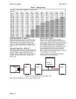
Zone Number Allocation 

The way in which zones can be provided by 
expanders depends on the presence or absence 
of KEY-KPZ01 keypads on the bus. 

Without KEY-KPZ01s: 

Only two of the 10-zone expanders connected to 
the system can have detectors associated with 
them. Similarly, only one 30-zone expander can 
have up to 20 zones allocated to it. 

With KEY-KPZ01s: 

With one to five KEY-KPZ01 keypads connected 
to the bus the control unit allocates zone numbers 
20 to 29 to the zones on the keypads. This means 
that zones 10 to 19 are available for use with 
expanders. If you connect more than five KEY-
KPZ01 keypads to the bus then the control unit 
allocates zone numbers 10 to 29 to keypad zones, 
and none are available for expanders. 

Communications 

The Menvier30 contains a built-in ATS2 
communicator, allowing it to comply with EN50131 
at Security Grade 2. 

The Menvier30 also provides sockets for an add-
on communication module. The available modules 
are: 

i-dig02 
(ATS2) 

A switched telephone network 
(PSTN) module that allows the 
control unit to report alarm 
information using standard 
protocols such as Fast Format, SIA 
and Contact ID, and can also send 
text messages over the Public 
Switched Telephone Network 
(PSTN). The i-dig02 also allows 
remote maintenance using 

Eaton’s 

Security Business Downloader 
software. 

i-sd02 
(ATS2) 

A speech dialler and PSTN module 
that allows the control unit to send 
recorded speech messages and 
report alarm information using 
standard protocols such as Fast 
Format, SIA and Contact ID. The 
module can also send text 
messages over the PSTN. The i-
sd02 also allows remote 
maintenance using 

Eaton’s Security 

Business Downloader software. 

i-gsm02 
(ATS2) 

A GSM module that allows alarm 
reporting, speech messaging and 
SMS text messaging over the 
mobile phone network. Note that a 
SIM card is not included with the 
module. 

Содержание MENVIER30

Страница 1: ...Menvier30 Security System Installation Guide Issue 2...

Страница 2: ...ing you to potential problems or hazards Each of these are marked by the words Note Caution or WARNING Note Describes conditions that may affect the proper functioning of the equipment but will not da...

Страница 3: ...eakers 21 Step 5 Connect Control Unit to Mains 21 Mains Cabling 21 Step 6 Connect Wired Zones 21 Four Wire Closed Circuit Connections 21 Two Wire Closed Circuit Connections 22 Fully Supervised Loop Co...

Страница 4: ...Menvier30 Page iv This page is intentionally blank...

Страница 5: ...a passive infra red detector smoke detector external siren 4 button remote control and remote radio keypad This control unit is designed and approved to be used as part of a Security Grade 2 system Zo...

Страница 6: ...of the Installer s programming menu please read Menvier30 40 100 300 Engineering Guide available from www coopersecurity co uk Installer Programming Interface Once fitted and powered up you can progr...

Страница 7: ...metal cabinets from their original position can all affect the signal from a transmitter Please read Eaton s Security Business publication Guidance Notes for Wireless Alarm System Installations obtai...

Страница 8: ...n metal or conducting films These glasses are particularly poor at transmitting radio waves Guided Tour CAUTION All printed circuit boards for the Menvier30 its expanders and keypads have been tested...

Страница 9: ...g by output connectors 4 Tamper switch connector 5 ADSL filter pins 6 On board communicator connections 7 Off hook LED 8 USB socket Mini B 9 Sockets for plug on module 10 Loudspeaker Bell and Strobe c...

Страница 10: ...envier30 Page 6 1 Built in communicator telephone line connector 2 Siren and strobe 3 Loudspeaker 4 Bus cable connector 5 Output transistorised 6 Aux power 7 Wired zone connectors Figure 4 Control Uni...

Страница 11: ...To open the keypad first gently prise off the trim on the front and remove the two screws Next carefully lever the front of the keypad containing the PCB and display away from the keypad rear housing...

Страница 12: ...push the bottom edge of the caps in with the end of a small screwdriver to start them Remove the two screws hidden underneath see Figure 9 Gently swing the lower side of the front out from the back bo...

Страница 13: ...r KEY EP Terminals for zones 4 Sounder volume control 5 Connector for data bus and output terminal 6 Jumpers for addressing and LED function 6a Addressing not used 6b LED functions and RS485 bus termi...

Страница 14: ...ker connectors 19 Outputs Figure 15 EXP W10 Wired Expander 1 Cable entry also behind PCB 2 Central keyhole 3 PCB 4 Relay card i rc01 connector 5 Aux power 6 Link to enable disable front rear tamper sw...

Страница 15: ...able front rear tamper switch 6 Lid tamper rear tamper behind PCB 7 Bus termination jumper 8 Addressing button 9 Fixing holes 10 Engineering keypad connector 11 Bus cable connector 12 Sounder 13 Louds...

Страница 16: ...example system and would meet the Grade 2 requirements Note All current drawn from the Aux terminals 12V must be included in the overall calculation CAUTION Ensure that the system does not demand more...

Страница 17: ...ain see Fig 18 In a star configuration If there are only two arms on the star then this is the same as a daisy chain configuration see Daisy Chain 1 in Figure 18 If required fit the termination jumper...

Страница 18: ...80mA 0 61V 1 22V 1 82V 2 43V 3 04V 3 65V 4 26V 4 86V 5 47V 6 08V 400mA 0 64V 1 28V 1 92V 2 56V 3 20V 3 84V 4 48V 5 12V 5 76V 6 40V Reducing Voltage Drop Method 1 Double up the supply connections 12V a...

Страница 19: ...ere must be enough space around this point to fit the supplied tamper shroud see Figure 21 Fitting Plastic Feet and Tamper Sleeve The control unit is supplied from the factory with four plastic feet a...

Страница 20: ...uring Screw When the PCB is in place connect the wires from the transformer to the 20Vac connector on the PCB 18 in Figure 3 Installing the Lid Back Tamper Figure 25 Lid Back Tamper Fit combined lid b...

Страница 21: ...ontrol systems If you mount prox readers closer together than one meter including on the other side of walls then the two prox readers will interfere and may not work correctly Fitting Keypads Select...

Страница 22: ...ng mode allows you to enable or disable the LEDs in the ABCD keys and the Navigation key It is possible to enter keypad programming mode when the keypad is not connected to a control unit but simply p...

Страница 23: ...any fault reports MENU STATUS FLT LED 4 Leave local programming mode and save your changes see below To Leave Local Programming Mode and Save Changes EITHER Press OR Close the keypad tamper The keypad...

Страница 24: ...gure 32 shows the wiring connections at the keypad Figure 32 Connecting the External Prox Reader Tone Volume All Keypads To alter the volume of non alarm tones from the keypad adjust the keypad sounde...

Страница 25: ...tions must be carried out by a qualified electrician and must comply with the current local regulations e g IEE Mains Cabling Note To avoid mains interference the mains cable must enter the control un...

Страница 26: ...r you can mimic the setting by using 4k7 2k2 4 wire CC zone wiring option and then connecting the detector to the alarm terminals and placing a short across the tamper terminals Fully Supervised Loop...

Страница 27: ...igure 43 shows the connections required Figure 43 Wiring Two Detectors per Zone FSL Figure 44 shows an example of wiring double doors with two door contacts to one FSL zone Each door contact is a reed...

Страница 28: ...ng Bell Tamper unnecessarily Wired Outputs on Expanders Each EXP W10 wired expander provides connections for up to four transistor driven outputs Each output has a maximum rating of 500mA but note tha...

Страница 29: ...as described above Figure 49 Wiring TR from External Sounder to a Zone on the Expander Remote Loudspeakers Optional If you wish to add a 16 Ohm wired Loudspeaker unit then connect it as shown in Figur...

Страница 30: ...th or without secondary proceed indication Note The built in communicator is not suitable for connection as an extension to a pay phone or to 1 1 carrier systems Approval The built in communicator is...

Страница 31: ...the authorised maintainer To connect the telephone line see Figure 52 i Using a two core telephone cable strip off 5mm and feed the cable through one of the entries marked 10 in Fig 2 in the rear of...

Страница 32: ...s present and 0V when the fault is absent Tell Back Input This input is designed to allow a plug by communicator to indicate to the control unit that the user can reset the system after a system tampe...

Страница 33: ...that the sudden noise does not startle you and cause a fall 1 Apply mains power to the control unit The keypads and internal sounder may give an alarm tone The heartbeat LED on the control unit PCB se...

Страница 34: ...s OK Two No communication over the bus in the last 10 seconds Three No bus address allocated to expander Four No poll request received from control unit in the last minute Transferring to Another Keyp...

Страница 35: ...tive If you need to re enter the Installer Menu 1 Make sure the system is unset and showing the standby screen time and date 2 Key in the Installer access code The default Installer access code is 123...

Страница 36: ...to display the desired wiring type on the bottom line of the display and then press to select it The system loads all defaults except for Access Codes and the Log The display briefly shows Followed b...

Страница 37: ...screw NOTE It is possible for convenience to place links over tamper contacts to inhibit tamper alarm for example during installation or if the unit is installed inside a larger tampered housing Beca...

Страница 38: ...ay Replies 2 Way Set Instant Duress Enable User reset Zone alarms 6 Zone tampers System tampers Confirmation Confirmation Mode Basic DD243 BS8243 Confirmation time 7 After entry 7 Entry keypad lock 7...

Страница 39: ...sabled 15 Appears only when Dynamic Test Call is disabled 16 Appears only if EXP PSU is fitted 17 Appears only if Report Mode Fast Format AND Confirmation Mode Basic 18 Shows None on Menvier30 If no c...

Страница 40: ...employ the Test Locate Bus Device option in the Installer Menu Use this option to make a selected bus device give a continuous tone from its sounder Once you have found the bus device you can silence...

Страница 41: ...ithout power Internal Clock 10 minutes over one year depending on the accuracy of the mains supply frequency User Codes 50 plus installer code Remote controls 50 one per user HUA Alarms 50 one per use...

Страница 42: ...e range 10 0 5V to 13 8V 12V Aux output voltage range 10 0 5V to 13 8V 12V Bell output voltage range 10 0 5V to 13 8V Max p to p ripple voltage 0 5V Standby Battery 12V 7Ah sealed lead acid not suppli...

Страница 43: ...726rEUR 60 Short range hand held HUD Detectors 713rEUR 00 Pet tolerant PIR 714rEUR 00 PIR Transmitter Small case 720rEUR 00 Smoke Detector Transmitter 734rEUR 00 01 CC FSL Door Contact Transmitter whi...

Страница 44: ...www coopersecurity co uk Product Support UK Tel 44 0 1594 541978 Available between 08 30 to 17 00 Monday to Friday Product Support Fax 01594 545401 email techsupport coopersecurity co uk Part Number 1...

Отзывы: