16
INM MTL 130-0126 Rev 13
5
CALIBRATION
5.1 General
The MTL katharometer based analysers are extremely stable instruments and require only
very occasional calibration. The exact calibration period depends on the type of sample and
environment the instrument is placed in. In practice it is unlikely that check periods of less
than one month would be necessary and three to six months would normally be in order. We
recommend that any quality assurance procedures written for the instrument are written to
allow verification as opposed to calibration. Verification involves checking that the instrument
provides the correct analysis of a standard gas within the limits of the instrument and only
calibrating when a result outside of limits is produced. The frequency of the verification would
need to be in line with the quality regime being operated by the user.
WARNING
The analogue output is set to 2mA (K1650) or 0v (K6050) while the instrument
is being calibrated. Ensure that any control loops that are connected to the
instrument are disabled prior to verifying or calibrating the instrument. Also
ensure that the process is in a safe state and the exhaust of the standard gas
is vented to a safe area. Calibration mode can only be entered by pressing the
Calibrate button for approximately 8 seconds whilst in Measurement Mode.
5.2 Piping
Ensure that the piping and connectors are of good quality with no possibility of leaks. Metal
piping is preferred as it is less prone to damage and sealing problems. Pressure regulators and
gauges that may be in the calibration gas lines all have a certain amount of dead space within
them and so may require purging for several minutes before the delivered gas matches that of
the cylinder contents. The regulator etc. may be connected to the instrument and the purge
monitored by using the instrument in measurement mode. Only when the reading is steady
has the dead space been purged.
NOTE
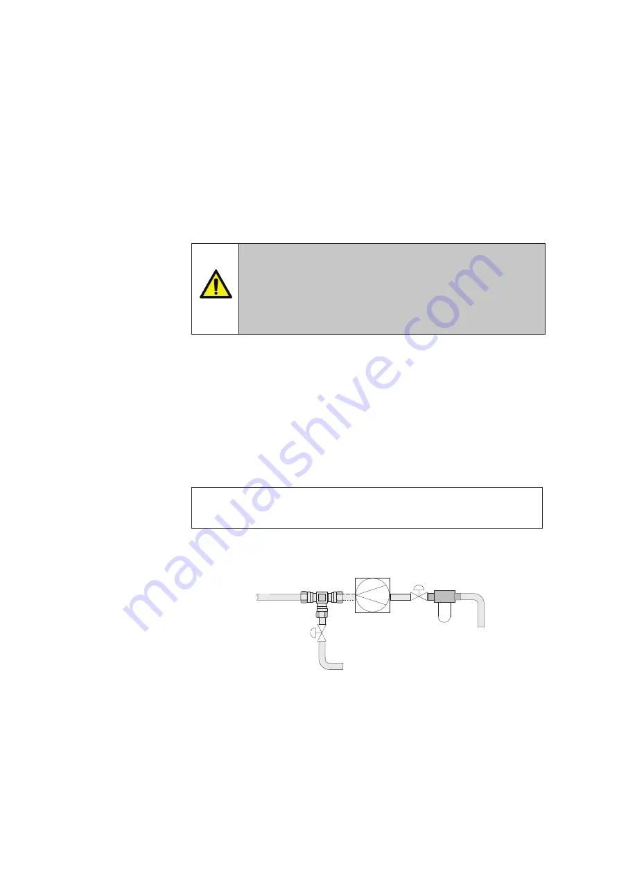
For permanent installations (K1650) in may be convenient to include a ‘T’ piece and
appropriate valves in the sample inlet line so that the calibration gas is easily connected.
Figure 11
- Sample and calibration gas piping
Calibration
Gas Inlet
To Process
Sample Connection
To Sample Inlet
Filter
Shut-off
Valve
Pump
-if required
Shut-off
Valve


