


18
Eaton Green Motion DC EV Charger User’s Manual P-164001189—Rev 01
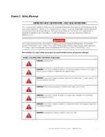
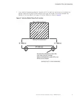
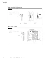
Figure 10. DC Charger Wiring Diagram
Legend:
A
Input voltage between two phases
B
Input voltage between phase and neutral
C
Upstream breaker in the power distribution board
D
DC EV Charger
B
A
N
L1
L2
L3
PE
D
C
To connect the charger to the electrical panel, a professional installer or qualified electrician should consider the
following guidelines and consult the table below.
Table 3. External Wiring and Upstream Protection Requirements
Charger rating
50 kW
75 kW
100 kW
125 kW
150 kW
Line cable size (AWG or Kcmil)
3
1/0
3/0
4/0
300
Line cable
Torque Rating N x m [lb-in]
14 Nm [124 lb-in]
Minimum ground cable size (AWG)
8
6
6
6
4
Ground
Torque Rating N x m [lb-in]
20 Nm [177 lb-in]
Circuit Breaker rating (A)
100
125
175
200
250
Table 4. Input Terminal Hardware Specification
Charger rating
50 kW
75 kW
100 kW
125 kW
150 kW
Line cable terminal block
M8
Ground cable terminal block
M8