Eaton Ferrups FX UPS P-164000906 Eaton Ferrups FX User’s Guide P-164000906—Rev 05
47
C
Chhaapptteerr 88 U
UP
PS
S S
Sttaarrttuupp
88..11
S
Sttaarrttuupp FFoorr H
Haarrddw
wiirreedd U
Unniittss
1.
The main circuit breaker in the load distribution panel should be off at this time.
2.
Confirm that an electrician has completed and tested the connection to the proper AC input power source.
3.
If your UPS has a DC switch, turn on the switch according to the UPS model:
•
FX3100 : The DC switch is located on the back of the UPS. If you have a external battery cabinet turn
the DC breaker located on the front of the battery cabinet to the ON position.
4.
At the UPS AC input service panel, turn on the input power to the UPS.
5.
If no alarms are present press and hold the UPS ON/OFF button for four seconds to turn the UPS on.
6.
In addition to the AC Line indicator the Ready, and Charging indicator will illuminate solid blue.
7.
Confirm that an electrician has completed and tested the connection from the UPS to your protected
equipment.
8.
Once the proper electrical connections have been verified to the load distribution panel the UPS is ready to
supply output power to the load equipment.
9.
The main circuit breaker in the load distribution panel can be turned on at this time.
88..22
IInniittiiaall S
Sttaarrttuupp ffoorr U
Unniittss IInnssttaalllleedd w
wiitthh aa B
BP
PEE B
Byyppaassss S
Sw
wiittcchh
After all hardwired connections are complete (including external battery cabinets, if applicable), complete the phase check
using the following steps. You will need an AC voltmeter for the phase check
Before operating the bypass switch, use the following procedure to check the wiring for correct installation. To
prevent damage to the load, turn off the main circuit breaker in the load service panel or verify that the load
cannot receive power from the UPS.
1.
Confirm that the electrician has completed and tested the connection to the proper power source.
2.
Verify that the bypass switch is in the OFF position.
3.
If your UPS has a DC switch, turn on the switch according to the UPS model:
•
3.1kVA: The DC switch is located on the back of the UPS. If you have an external battery cabinet turn
the DC breaker located on the front of the battery cabinet to the ON position.
4.
At the UPS AC input service panel, turn on the input power to the UPS and the bypass switch.
5.
Turn on the Bypass AC disconnect switch.
6.
Turn the bypass switch to the UPS position.
7.
If no alarms are present on the UPS press the UPS ON/OFF button for four seconds to turn the UPS on.
8.
In addition to the AC Line indicator, the Ready, and Charging indicator will illuminate solid blue. The UPS is
ready to supply output power.
•
The main circuit breaker in the load distribution panel should be off at this time.
9.
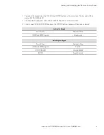
Use an AC voltmeter to measure voltages on the terminal strip inside the bypass switch cabinet (refer to
the label on the back of the switch’s lower front cover for the terminal numbers). record your
measurements in the following chart according to the type of bypass switch installed. The voltages in the
Содержание Ferrups FX
Страница 1: ...p n P 164000906 Revision 05 Ferrups FX UPS Eaton Ferrups FX User s Guide Eaton Ferrups FX UPS...
Страница 8: ...viii Eaton Ferrups FX UPS P 164000906 Eaton Ferrups FX User s Guide P 164000906 Rev 05 List of Figures...
Страница 18: ...8 Eaton Ferrups FX UPS P 164000906 Eaton Ferrups FX User s Guide P 164000906 Rev 05 Communication Overview...
Страница 82: ...72 Eaton Ferrups FX UPS P 164000906 Eaton Ferrups FX User s Guide P 164000906 Rev 05 Service and Support...
Страница 88: ...78 Eaton Ferrups FX UPS P 164000906 Eaton Ferrups FX User s Guide P 164000906 Rev 05 Battery...
Страница 90: ...P 16400090605 P 164000906 05...

