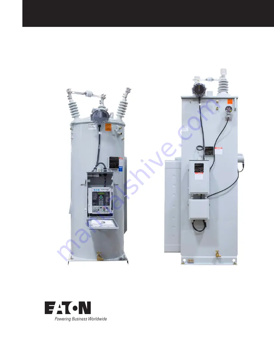
VR-32 and EVER-Tap™ Voltage Regulator
Installation, Operation, and Maintenance Instructions
COOPER POWER
SERIES
Voltage Regulators
MN225008EN
Effective June 2020Supersedes February 2017
Страница 1: ...VR 32 and EVER Tap Voltage Regulator Installation Operation and Maintenance Instructions COOPER POWER SERIES Voltage Regulators MN225008EN Effective June 2020 Supersedes February 2017 ...
Страница 2: ...T IN ANY EXISTING CONTRACT BETWEEN THE PARTIES ANY SUCH CONTRACT STATES THE ENTIRE OBLIGATION OF EATON THE CONTENTS OF THIS DOCUMENT SHALL NOT BECOME PART OF OR MODIFY ANY CONTRACT BETWEEN THE PARTIES In no event will Eaton be responsible to the purchaser or user in contract in tort including negligence strict liability or otherwise for any special indirect incidental or consequential damage or lo...
Страница 3: ...ngers 19 EVER Tap voltage regulators 21 EVER Tap important operational information 22 MAINTENANCE 23 Quik Drive tap changers 23 EVER Tap voltage regulator 24 Operational check 25 Insulating fluid maintenance 26 EVER Tap voltage regulator insulating fluid maintenance 26 Sampling insulating fluid 26 FR3 insulating fluid application 26 Untanking the regulator 27 Retanking the regulator 28 SPARE PARTS...
Страница 4: ... hazardous situation which if not avoided could result in death or serious injury CAUTION Indicates a potentially hazardous situation which if not avoided may result in minor or moderate injury NOTICE Indicates a potentially hazardous situation which if not avoided may result in equipment damage only Safety instructions Following are general caution and warning statements that apply to this equipm...
Страница 5: ...gs should all be inspected for evidence of damage Should this initial inspection reveal evidence of rough handling damage or shortages it should be noted on the bill of lading and a claim should immediately be made with the carrier Also notify your Eaton representative Handling and storage Be careful during handing and storage of equipment to minimize the possibility of damage If the regulator wil...
Страница 6: ...ndard features CL 7 voltage regulator control CE mark compliant Dual rated 55 65 C average winding rise Measure load and source voltages ADD AMP capability Sealed tank construction Pressure relief device 18 minimum creep bushings with clamp type connectors MOV type external series arrester Shunt arrester mounting bosses Two aluminum laser etched nameplates Insulating fluid 25 C level sight gauge C...
Страница 7: ...ing bracket units up to 250 kVA Drain valve and insulating fluid sampling device Ground pad Junction box Hand hole cover Cover Position indicator Shunt arrester mounting bosses Control cable with Quick Disconnect plug Lockable control enclosure Tap changer motor capacitor Control ground boss Bolt down provisions 4 Substation base available in units 167 kVA and above Figure 2 External features of t...
Страница 8: ...neutral For Delta connections connect the SL bushing to the appropriate phase Inaccurate connections may cause excessively high or low voltage on the load side of the regulator and can cause death or severe personal injury and equipment damage A regulator can regulate a single phase circuit or one phase of a three phase wye star or delta circuit Two regulators connected phase to phase in open delt...
Страница 9: ...6 Regulating a three phase four wire multi grounded wye star circuit with three regulators Wye A B C Source Load Control Box Control Box Control Box Figure 7 Regulating a three phase three wire circuit with three regulators Closed Delta 5 VR 32 and EVER Tap Voltage Regulator Installation Operation and Maintenance Instructions MN225008EN June 2020 ...
Страница 10: ...ice or support related issues have the catalog number and serial number found on the nameplate for reference Mounting Regulators with over head bushings can be mounted on a pole a cross arm platform or an elevating structure Regulators are normally provided with either pole mounting brackets or a substation base according to their rating An elevating structure can be provided to simplify substatio...
Страница 11: ...Figure 9 Typical nameplate international 50 Hz design 7 VR 32 and EVER Tap Voltage Regulator Installation Operation and Maintenance Instructions MN225008EN June 2020 ...
Страница 12: ...ontrol Installation Operation and Maintenance Instructions for information on the CL 7 voltage regulator control including placing the control into service and initial programming As with all electrical equipment proper grounding of a voltage regulator control box is essential The voltage regulator control box must be grounded to the tank ground pad or earth ground A poor ground connection to the ...
Страница 13: ...tor dial pointer is pointing directly at N or 0 for neutral d Measure the voltage difference between the S and L bushings using an approved voltmeter or the SAFE TO BYPASS feature on the CL 7 control The voltage should measure zero or very close to zero 9 With regulator in neutral position disable the motor operation by taking the following steps a Set the CONTROL FUNCTION switch to OFF b Set the ...
Страница 14: ...intenance Instructions for information on the CL 7 voltage regulator control including placing the control into service and initial programming Setting the manual hard limit switches Note N Refer to Position indicator and ADD AMP capability on page 13 for a complete discussion of these features Before setting the manual limit switches be sure the new settings will not conflict with the present tap...
Страница 15: ...the Neutral light will be continuously and brightly lit on the control front panel and the position indicator will point to zero or N for Neutral 2 Verify the neutral position of the regulator using each of these four methods a Verify that the neutral indicator light on the control is indicating the neutral position Neutral is indicated only when the light is continuously and brightly illuminated ...
Страница 16: ...and hole cover A hand hole on the cover of the regulator provides access for inspection purposes and to access terminals used to reconnect the regulator for operation at system voltages as shown in Table 9 page 36 and Table 10 page 37 Mounting Regulators rated 250 kVA and below are provided with welded on hanger brackets Regulators rated 167 kVA and above are provided with a base suitable for secu...
Страница 17: ...are not recommended The raise and lower limits need not be the same value unless reverse power is possible The regulator will stay within the ADD AMP limits set forth by the control or the position indicator whichever limit is of a lower regulation percentage Note N If Soft ADD AMP limits have been programmed into the control and the position indicator limit switches have not been set it is possib...
Страница 18: ...s a voltage for the tap changer motor and the control sensing circuit Additional taps are available in the PT for line voltages other than rated voltage Most regulators depending upon the rating have an equalizer winding This winding improves contact life for high current applications Figure 16 shows a typical regulator power circuit with a series transformer This design is utilized when the load ...
Страница 19: ...inding located on the source side ANSI Type B 1 2 3 4 5 6 7 8 VR VL N SL S L E3 E2 E1 E CONTROL V1 G C2 C1 Source Load Figure 15 Power circuit series winding located on the load side ANSI Type A 15 VR 32 and EVER Tap Voltage Regulator Installation Operation and Maintenance Instructions MN225008EN June 2020 ...
Страница 20: ...ries auto transformer Type AX similar characteristics to Type A 8 VL SL S L E3 E2 E1 E CONTROL V1 G C2 C1 Source Load 7 6 5 4 2 1 3 N VR Figure 17 Power circuit series transformer Type TX 16 VR 32 and EVER Tap Voltage Regulator Installation Operation and Maintenance Instructions MN225008EN June 2020 ...
Страница 21: ...performance a regulator installed on such a circuit should have the capability of detecting reverse power flow and of sensing and controlling the voltage regardless of the power flow direction The CL 7 control has full reverse power capabilities Refer to Service Information MN225003EN CL 7 Voltage Regulator Control Installation Operation and Maintenance Instructions for more information on the CL ...
Страница 22: ... from the 6 A fuse to the circuit board through a set of back to back diodes to the CONTROL FUNCTION switch When this switch is set for automatic operation motor power is applied to the relays An appropriate relay closure then applies this power to the tap changer motor after first passing through the limit switch contacts in the position indicator When the switch is set for manual operation the p...
Страница 23: ...itch A common holding switch assembly driven by a pinion cam seals in motor power during a tap change until the operation is complete Position Indicator Drive A common indexing mechanism is shared between the tap changers for driving the Position Indicator Safety Switches In addition to the limit switches in the Position Indicator microswitches are employed on the tap changers to interrupt power t...
Страница 24: ...us motor uses a 12 µF capacitor for 60 Hz applications and a 15 µF capacitor for 50 Hz applications The induction motors use a phase shifting capacitor and require a friction type brake to stop the motor between tap changes Brakes use various means to interrupt the braking action while the movable contacts are in motion so that full motor torque is dedicated to completing the tap change The induct...
Страница 25: ...tion back to neutral 14 If the tap changer is switching from position 15 to position 16 a normally closed limit switch is triggered that is connected in parallel with the logic switch Both the limit switch and the logic switch open up so that the control cannot make a tap change past position 16 EVER Tap voltage regulators The EVER Tap voltage regulator utilizes a VACUTAP RMV SVR I 2000 tap change...
Страница 26: ...itch is in position B When the tap selector moves between the neutral position and position 1 Lower the reversing switch moves between position A and B EVER Tap important operational information WARNING The user of this equipment should be properly trained in the operation of voltage regulators Wiring and operation of the EVER TAP voltage regulator is different than other voltage regulators equipp...
Страница 27: ...es from the CL 7 and locks out further input until the end of the tap change cycle so a brief actuation of the raise lower switch in MANUAL mode is enough to start and complete a tap change It is acceptable to hold the raise lower switch in one position if multiple tap changes are to be made in the same direction Before reversing the direction of operation of the tap changer wait for the completio...
Страница 28: ... compare the results to the requirements found in Table 5 and Table 6 Related manuals Review the following tap changer manuals for additional information on contact erosion and tap changer maintenance requirements MN225072EN QD3 Quik Drive Voltage Regulator Tap Changer Manual MN225012EN QD5 Quik Drive Voltage Regulator Tap Changer Manual MN225011EN QD8 Quik Drive Voltage Regulator Tap Changer Inst...
Страница 29: ...components Inspect the tap changer mechanism and motor drive unit for worn components including bearings cams pins and microswitches Replace worn components Duty Cycle Monitor DCM This feature is not available for the EVER Tap voltage regulator Operational check Proper operation of the regulator can be checked without removing the unit from service To perform an operational check 1 Place the CONTR...
Страница 30: ...p 45 25 40 23 Interfacial Tension mNm ASTM D971 91 Water mg kg ASTM D1533 300 b a Per IEEE Std C57 147 2008 standard b Recommended limit is application and user specific Suggested limit would be the same relative saturation limit used for mineral oil at a given temperature Table 6 Mineral Oil Characteristics Type IIa Characteristic New Used Dielectric Strength kV ASTM D1816 2 mm gap 1 mm gap 45 25...
Страница 31: ...record the position indicator reading before proceeding so the position indicator can be returned to the correct position before retanking 2 Disconnect the control cable from the bottom of the junction box see Figure 1 3 Remove the series arrester to avoid damaging the arrester and bushings while lifting the internal components 4 Release the tank pressure by pulling the ring on the pressure relief...
Страница 32: ...ion is reached then tighten the set screw c Verify coordination of the position indicator with the tap changer in the neutral position control neutral light on 3 Check the gasket seat surfaces on the cover and tank and wipe clean Wipe the gasket and position it on the tank lip 4 Loosen the horizontal side channel bolts to ensure proper seating of the regulator in the tank and proper cover seal 5 R...
Страница 33: ...aintenance Instructions The procedures in this section provide terminal markings for a single phase control If troubleshooting is being performed on a regulator with a multi phase control the terminals corresponding to the phase in question should be used See Table 7 for assistance in identifying the correct terminals Table 7 Single phase and multi phase control back panel markings Single Phase Co...
Страница 34: ...hings and increase the applied voltage until 50 of the current rating is reached this should be around 55 V 11 Depending on the polarity of the voltage applied to the L and SL bushings the control will operate in either the forward or reverse power flow direction If the control REVERSE POWER LED does not illuminate the control is in the forward mode Reversing the voltage source leads on the L and ...
Страница 35: ...he equalizer winding Note N On a type B regulator the difference between the taps will be slightly less than calculated as the regulator is tapped toward 16 Lower This is normal and inherent in the design of the type B regulator Questions about the described procedure may be directed to your Eaton representative Voltage regulator potential transformer ratio test Purpose The purpose of this test is...
Страница 36: ...e current in the shorted current path WARNING Hazardous Voltage The regulator tank must be solidly earth grounded Failure to comply can cause severe personal injury and equipment damage 5 Ground the regulator tank 6 Using a variac apply impedance voltage at 16 Raise between the S and L bushings Raise the voltage until rated current is read on the ammeter Impedance voltage values may be obtained fr...
Страница 37: ...test WARNING Hazardous Voltage The regulator tank must be solidly earth grounded Failure to comply can cause severe personal injury and equipment damage 5 Ground the regulator tank 6 Close C knife switch on the back panel 7 Remove the jumper from between the C2 and C3 terminals to the left of the V1 switch on the back panel See Figure 25 Place a milli ampere meter between these terminals See Figur...
Страница 38: ...the reading with the baseline reading If the new reading is lower than the baseline reading further testing and evaluation of the insulation is recommended Note N This test is very sensitive to contamination on the regulator bushings If the new reading is the same as or higher than the baseline reading no further testing is indicated Freeing a stalled tap changer Purpose The purpose of this proced...
Страница 39: ... switch 18 Place the POWER switch on INTERNAL 19 Turn CONTROL FUNCTION control switch to LOCAL MANUAL 20 Using the RAISE LOWER switch step the regulator to the neutral position 21 Before de energizing the regulator by bypassing to remove it from service verify that the regulator is in the neutral position It is recommended that you perform a minimum of four checks to confirm that the voltage regul...
Страница 40: ...1 P1 120 1 110 120 110 1 12000 E1 P1 120 1 104 115 5 104 1 7970 E2 P2 60 1 133 120 65 5 1 7620 E2 P2 60 1 127 120 63 5 1 7200 E2 P2 60 1 120 120 60 1 6930 E2 P2 60 1 150 120 5 57 5 1 19920 19920 E1 P1 166 1 120 120 166 1 17200 E1 P1 166 1 104 119 5 143 9 1 16000 E2 P2 120 1 133 120 5 133 1 15242 E2 P2 120 1 127 120 127 1 14400 E2 P2 120 1 120 120 120 1 7970 E3 P3 60 1 133 120 65 5 1 7620 E3 P3 60 ...
Страница 41: ... 118 9 84 1 1 6600 E3 P3 53 8 1 120 122 7 53 8 1 22000 22000 E1 P1 183 4 1 120 120 0 183 4 1 20000 E1 P1 183 4 1 110 119 0 168 1 1 19100 E1 P1 183 4 1 104 120 2 158 9 1 15000 E2 P2 122 3 1 120 122 7 122 3 1 12700 E2 P2 122 3 1 104 119 9 106 0 1 11000 E3 P3 91 7 1 120 120 0 91 7 1 10000 E3 P3 91 7 1 110 119 0 84 0 1 33000 33000 E1 P1 275 0 1 120 120 0 275 0 1 30000 E1 P1 275 0 1 110 119 0 252 1 1 2...
Страница 42: ... 440 480 540 640 667 483 531 580 652 668 833 604 664 668 668 668 Table 11 continued Rated Volts Rated kVA Load Current Ratings A a Regulation Range Wye and Open Delta 10 8 75 7 5 6 25 5 Regulation Range Closed Delta 15 13 1 11 3 9 4 7 5 14400 72 50 55 60 68 80 144 100 110 120 135 160 288 200 220 240 270 320 333 231 254 277 312 370 416 289 318 347 390 462 432 300 330 360 405 480 500 347 382 416 468...
Страница 43: ... 160 225 150 165 180 203 240 300 200 220 240 270 320 450 300 330 360 405 480 600 400 440 480 540 640 750 500 550 600 668 668 16000 160 100 110 120 135 160 320 200 220 240 270 320 22000 110 50 55 60 68 80 220 100 110 120 135 160 330 150 165 180 203 240 440 200 220 240 270 320 660 300 330 360 405 480 880 400 440 480 540 640 33000 165 50 55 60 68 80 330 100 110 120 135 160 495 150 165 180 203 240 333...
Страница 44: ...ing diagrams Figure 27 Typical internal wiring of voltage regulators with a QD3 tap changer 40 VR 32 and EVER Tap Voltage Regulator Installation Operation and Maintenance Instructions MN225008EN June 2020 ...
Страница 45: ...Figure 28 Typical internal wiring of voltage regulators with QD5 and QD8 tap changers 41 VR 32 and EVER Tap Voltage Regulator Installation Operation and Maintenance Instructions MN225008EN June 2020 ...
Страница 46: ...7 2 4 5 6 1 1 1 2 1 3 Figure 29 Typical internal wiring of EVER Tap voltage regulator tap changer 42 VR 32 and EVER Tap Voltage Regulator Installation Operation and Maintenance Instructions MN225008EN June 2020 ...
Страница 47: ...LEX 3 PIN 1 2 RECEPTACLE D MOLEX 2 PIN 1 2 PLUG D MOLEX 2 PIN LLS 2 GRN BLK RLS 2 BLU A BLU A GRN BLK STUD 1 2 3 4 5 6 7 8 9 10 11 BLK BLK WHT LT BLU BLK ORN RED BLK WHT BLK GRN BLK BLU POS 3 BLK WHT GROUND WHT POS 9 BLU POS 10 GRN BLK POS 4 LT BLU BLK POS 6 RED BLK POS 5 ORG CABLE ASSY CC 12 CONNECTION RECEPTACLE INTERNAL MOLEX 12 PIN 1 2 C C POS 8 WHT POS 7 BLK POS 2 BLK J B 3 8 STUD WHT RS 2 WH...
Страница 48: ...WHT BLK LLS 2 GRN BLK CC ORG RLS 2 BLU CC BLK CC RED CC ORG BLK RS 1 ORG BLK 2 1 2 1 2 1 JUNCTION BOX TERMINAL BOARD GROUND GREEN RED DHR S2 R C1 C2 NL M2 G HS S7 S6 L S4 CC BLU BLK CC BLK WHT STUD GROUND STUD JBB INDICATOR POSITION SOLENOID RESET RS Figure 31 Legacy junction box wiring diagram 44 VR 32 and EVER Tap Voltage Regulator Installation Operation and Maintenance Instructions MN225008EN J...
Страница 49: ...OR CC BLU BLK CC BLK WHT 12 WHT CC WHT 20 WHT BRN 16 BLK 19 RED 18 GRN CC ORG 14 BLU 15 WHT GRN CC RED BLK CC ORG BLK 1 2 3 3 1 2 4 4 7 6 5 10 BLK CC BLK CC GRN 19 RED 17 VIO CC RED V6 1 2 3 4 CC WHT BLK NOTE 1 NOTES 1 LEAD 20 WHT BRN CONNECTS V6 4 TO V7 INSTEAD OF VS TO V7 WHEN A DIFFERENTIAL PT IS UTILIZED NOTE 2 2 CONTROL CABLES CONTAINING 14 CONDUCTORS WILL HAVE CAPACITOR WIRE COLORS OF RED WH...
Страница 50: ... CC WHT 16 BLK 19 RED 18 GRN 14 BLU 15 WHT GRN CC RED BLK CC ORG BLK 1 2 3 3 1 2 4 4 7 6 5 10 BLK CC BLK CC GRN 19 RED 17 VIO CC RED V6 2 3 4 CC WHT BLK V8 2 3 4 V2 2 3 4 RLS LLS OCI 3 2 1 ABP CC BLU BLK CC BLK WHT 20 WHT BRN BRAKING CAPACITOR AB RED WHT AB BLU WHT CC BLU CC GRN BLK CC ORG AB YEL AB WHT AB BLU AB ORG AB RED AB BLK AB WHT AB RED WHT CC RED WHT AB GRN WHT CC GRN WHT ACTUATOR BOARD H...
Страница 51: ...This page is intentionally left blank T 47 VR 32 and EVER Tap Voltage Regulator Installation Operation and Maintenance Instructions MN225008EN June 2020 ...
Страница 52: ...United States Eaton com cooperpowerseries 2020 Eaton All Rights Reserved Printed in USA Publication No MN225008EN June 2020 Eaton is a registered trademark All trademarks are property of their respective owners For Eaton s Cooper Power series product information call 1 877 277 4636 or visit www eaton com cooperpowerseries SAFETY FOR LIFE ...