


51
645M 4G/LTE CELLULAR ROUTER
MN032003EN March 2017 www.eaton.com
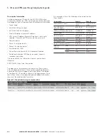
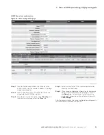
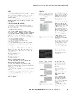
Step 6
When the IPsec tunnel is established, all IP Packet
traffic originating from 192. 32. 8.254/32 will pass
through the IPsec VPN tunnel to the local subnet
(10.192.10.192/29), and vice-versa. Click the View link
in the far-right column of the table to monitor the
IPsec client connection. A window opens to display
the log of the tunnel’s negotiation activity (early
events appear near the top and more-recent events
appear near the bottom). Search the log contents for
“IPsec SA established tunnel mode.”
002 “ttunnel1” #1: initiating Main Mode
104 “ttunnel1” #1: STATE_MAIN_I1: initiate
003 “ttunnel1” #1: ignoring Vendor ID payload
[FRAGMENTATION c0000000]
002 “ttunnel1” #1: transition from state STATE_MAIN_I1 to
state STATE_MAIN_I2
106 “ttunnel1” #1: STATE_MAIN_I2: sent MI2, expecting MR2
003 “ttunnel1” #1: received Vendor ID payload [Cisco-Unity]
003 “ttunnel1” #1: received Vendor ID payload [XAUTH]
003 “ttunnel1” #1: ignoring unknown Vendor ID payload
[d194db099684f49320f6abd9829c7b65]
003 “ttunnel1” #1: ignoring Vendor ID payload
[Cisco VPN 3000 Series]
002 “ttunnel1” #1: transition from state STATE_MAIN_I2 to
state STATE_MAIN_I3
108 “ttunnel1” #1: STATE_MAIN_I3: sent MI3, expecting MR3
003 “ttunnel1” #1: received Vendor ID payload
[Dead Peer Detection]
002 “ttunnel1” #1: Main mode peer ID is ID_IPV4_ADDR:
‘10.168.86.192’
002 “ttunnel1” #1: transition from state STATE_MAIN_I3 to
state STATE_MAIN_I4
004 “ttunnel1” #1: STATE_MAIN_I4: ISAKMP SA established
{auth=OAKLEY_PRESHARED_KEY
cipher=oakley_3des_cbc_192 prf=oakley_
md5 group=modp1024}
002 “ttunnel1” #1: Dead Peer Detection (RFC 3706): enabled
002 “ttunnel1” #2: initiating Quick Mode PSK+ENCR
YPT+UP+IKEv2ALLOW
{using isakmp#1 msgid:4328edc8
proposal=3DES(3)_192-MD5(1)_128
pfsgroup=no-pfs}
117 “ttunnel1” #2: STATE_QUICK_I1: initiate
003 “ttunnel1” #2: ignoring informational payload, type IPSEC_
RESPONDER_LIFETIME msgid=4328edc8
002 “ttunnel1” #2: Dead Peer Detection (RFC 3706): enabled
002 “ttunnel1” #2: transition from state STATE_QUICK_I1 to
state STATE_QUICK_I2
004 “ttunnel1” #2: STATE_QUICK_I2: sent QI2, IPsec
SA established tunnel mode
{ESP=>0x8e426351 <0xaeeb3b44
xfrm=3DES_0-HMAC_MD5 NATOA=none
NATD=none DPD=enabled}
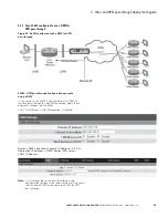
Step 8
Once the “IPsec SA established tunnel mode”
message is displayed in the tunnel negotiation log,
a communication test is required to ensure point-to-
point connectivity. From the Application Server located
behind the VPN server, ping the LAN IP of the local
device connected to the ELPRO 645M LAN port. The
pings should receive replies from the local device.
Alternatively, ping the Application Server IP Address from a
device on the 645M’s local LAN and receive replies similar to
the following.
[Prompt]$ping 192.32.8.254
PING 192.32.8.254 (192.32.8.254) from 10.192.10.195
64 bytes from 192.32.8.254: seq=0 ttl=126 time=136.646 ms
64 bytes from 192.32.8.254: seq=1 ttl=126 time=134.848 ms
64 bytes from 192.32.8.254: seq=2 ttl=126 time=135.274 ms
64 bytes from 192.32.8.254: seq=3 ttl=126 time=133.018 ms
^C
--- 192.32.8.254 ping statistics ---
4 packets transmitted, 4 packets received, 0% packet loss
round-trip min/avg/max = 133.018/134.946/136.646
Repeat the above steps to configure and enable the second
tunnel.
Edit and Delete buttons in the table allow you to change
configuration settings or remove the tunnel the Tunnel Table. You
can also select a tunnel to configure by simply typing its name
in the
Name
field.
•
To change settings, enter the Tunnel Item number in the
Tunnel Configuration section, enter the configuration
settings, and click
Save & Apply
.
•
To delete a tunnel, click the
Delete
button in the far-right
column that is associated with the tunnel item.
5 IPsec and VPN pass-through deployment guide