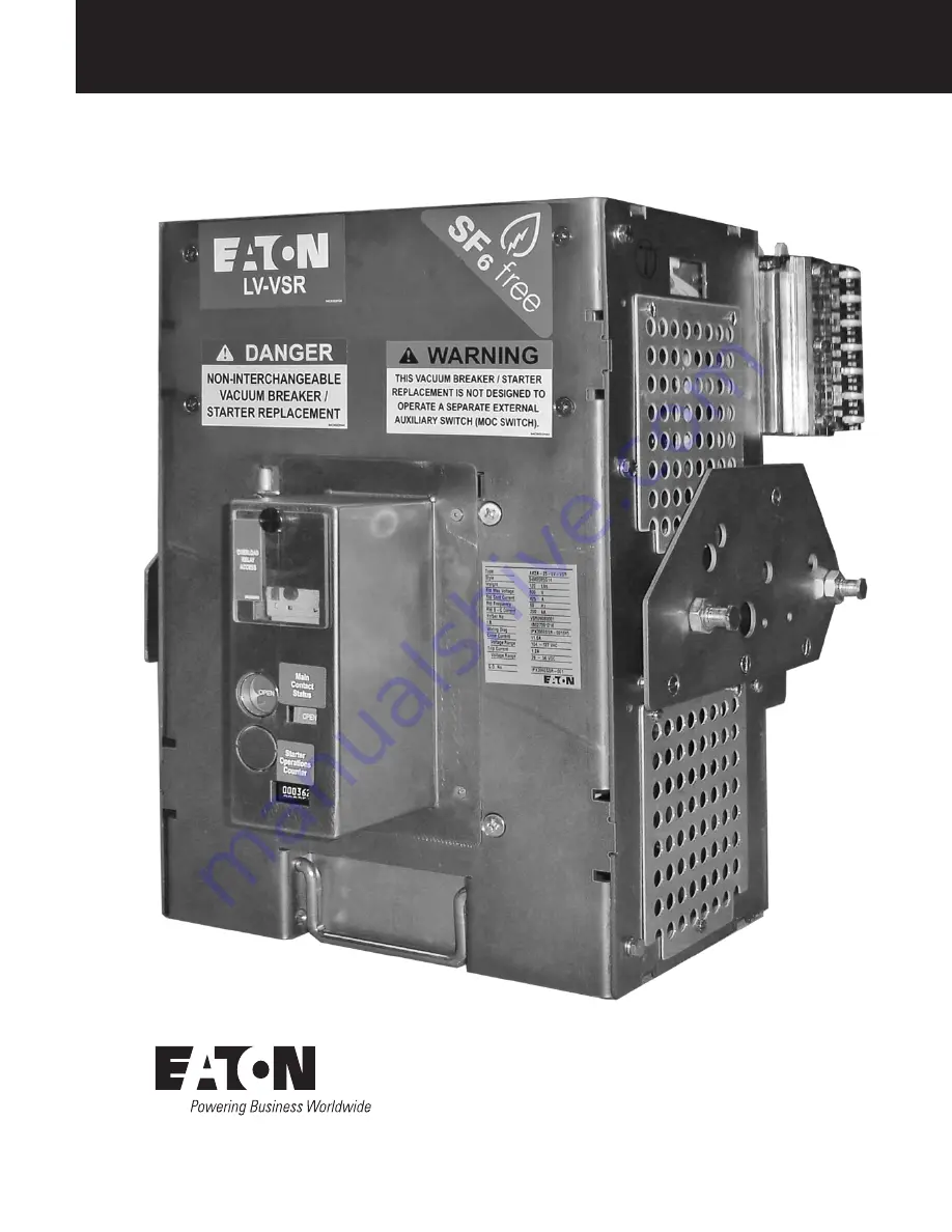
Instruction Book IB019009EN
AK-2A-25-LV-VSR 425A Shown
November 2017
Supersedes July 2017Effective
AK-2-25, AK-2A-25, & AK-3A-25 LV-VSR
Breaker-To-Motor Starter Conversion
Страница 1: ...Instruction Book IB019009EN AK 2A 25 LV VSR 425A Shown November 2017 Supersedes July 2017 Effective AK 2 25 AK 2A 25 AK 3A 25 LV VSR Breaker To Motor Starter Conversion ...
Страница 2: ...ns of this equipment do not purport to be covered by these instructions If further information is desired by purchaser regarding his particular installation operation or maintenance of particular equipment contact a local Eaton representative DISCLAIMER OF WARRANTIES AND LIMITATION OF LIABILITY The information recommendations descriptions and safety notations in this document are based on Eaton s ...
Страница 3: ...6 5 3 MANUAL OPERATIONAL CHECK 18 5 4 ELECTRICAL OPERATIONAL CHECKS 18 SECTION 5 A INSTALLATION OF AK 2 25 LV VSR 19 5 A 1 CELL MODIFICATION INSTRUCTIONS 19 5 A 2 COMPARTMENT DOOR MODIFICATIONS 19 5 A 3 INSERTION PROCEDURE 20 5 A 4 REMOVAL PROCEDURE 21 SECTION 5 B INSTALLATION OF AK 2A 25 LV VSR 22 5 B 1 CELL MODIFICATION INSTRUCTIONS 22 5 B 2 INSERTION PROCEDURE 22 5 B 3 REMOVAL PROCEDURE 23 SECT...
Страница 4: ...on through the use of micro electronic packaging technology The Overload Relay comes standard with Trip Class 10 15 and 20 trip characteristics and Manual or Manual Automatic Reset The V201 Vacuum Contactor is designed for the control of inductive or non inductive loads at voltages between 200 and 600 ac The fuses have a micro switch mounted to the body of the fuse which provides blown open indica...
Страница 5: ...aton com AK 2 25 AK 2A 25 AK 3A 25 LV VSR Breaker To Motor Starter Conversion Table 2 AK 2 25 LV VSR Dimensions Device Type Existing Breaker Rated Continuous Current at 60 Hz Amps A B C D E F G AK 2 25 LV VSR 425A 18 05 3 50 5 00 8 00 20 41 17 10 3 55 ...
Страница 6: ...otor Starter Conversion E G F C D A B B Table 3 AK 2A 25 AK 3A 25 LV VSR Dimensions AK 2A 25 LV VSR Shown Device Type Existing Breaker Rated Continuous Current at 60 Hz Amps A B C D E F G AK 2A 25 LV VSR 425A 16 29 3 50 4 50 8 12 20 19 18 00 3 55 AK 3A 25 LV VSR 425A 16 29 3 50 4 50 8 12 20 19 18 00 3 55 ...
Страница 7: ...ve the LV VSR from the enclosure before performing any maintenance Failure to do so could result in electrical shock leading to death severe personnel injury or property damage Do not work on a LV VSR with the secondary test coupler engaged Failure to disconnect the test coupler could result in an electrical shock leading to death personnel injury or property damage Do not use a LV VSR as the sole...
Страница 8: ...idual pipe rollers Once a LV VSR has been inspected for shipping damage it is best to return it to its original shipping crate until it is ready to be installed in the Metal Enclosed Switchgear When a LV VSR is ready for installation a lifting harness in conjunction with an overhead lift or portable floor lift can be used to move a LV VSR If the LV VSR is to be lifted position the lifting device l...
Страница 9: ...Starter Conversion Front External View 1 Overload Relay Access 5 Racking Handle 9 Guide Rail 2 Open Operator 6 Lifting Point 10 Lock Out Tag Out 3 Contactor Status Indicator 7 Secondary Contacts 4 Contactor Operations Counter 8 Handle Pins Figure 3 2 Front External View of AK 2 25 LV VSR 1 8 9 10 6 7 3 2 4 5 ...
Страница 10: ...A 25 AK 3A 25 LV VSR Breaker To Motor Starter Conversion Rear External View 1 Secondary Contacts 4 Guide Rail 7 Handle Pins 2 Primary Disconnects 5 Rear Position Stop 3 V201 Vacuum Contactor 6 Lifting Point Figure 3 3 Rear External View of AK 2 25 LV VSR 2 5 4 3 1 1 7 4 6 ...
Страница 11: ...Breaker To Motor Starter Conversion Figure 3 4 Front External View of AK 2A 25 LV VSR 1 8 8 5 6 7 3 2 4 Front External View 1 Overload Relay Access 4 Contactor Operations Counter 7 Secondary Block Shim 2 Open Operator 5 Lifting Point 8 Rollers 3 Contactor Status Indicator 6 Secondary Contacts ...
Страница 12: ... 25 AK 2A 25 AK 3A 25 LV VSR Breaker To Motor Starter Conversion Figure 3 5 Rear External View of AK 2A 25 LV VSR 2 3 1 1 1 5 6 5 4 Rear External View 1 Secondary Contacts 3 V201 Vacuum Contactor 5 Rollers 2 Primary Disconnects 4 Lifting Point 6 Code Pin 425A Shown ...
Страница 13: ...environment immune coil shell which also contains a full wave bridge When ac is connected directly to terminals A and B on the coil shell the magnet excitation is unfiltered dc The magnet will not chatter as ac magnets sometimes do but at less than rated voltage it may hum slightly A normally closed Type L63 auxiliary contact set to open slightly before the armature fully closes is connected to te...
Страница 14: ...C VSR SECONDARY CONTACT PIN NUMBER POSITION SWITCH CLOSED IN TEST AND TEST AND CONNECT CONNECT POSITIONS OPEN IN BETWEEN LEGEND FU Ma CS C CS T R S R B A L63 COIL AUX CONT M MR1 C D T MR1 A1 A2 OL PS1 Y AOS S A Y 7 8 T Y Mb T 7 8 Ma a MR1 a MR1 a MR1 a MR1 b MR1 b MR1 b 33 51 61 71 72 62 52 34 24 n o n o n c n c 6 4 4 6 C1 N C 95 96 43 44 13 14 n o n o 5 1 5 1 N C C T TRIP OPEN RELAY Ma CONTACTOR ...
Страница 15: ...uses can interrupt faults up to 200 000 Amperes RMS symmetrical current The fuses are Ferraz Shawmut type J AJT600EIB current limiting DO NOT replace the fuses with any other type fuse The fuses have been tested in conjunction with the V201 vacuum contactor Blown Fuse Indication The fuses have a micro switch mounted on the body of the fuse This switch activates when a fuse blows If the LV VSR expe...
Страница 16: ... in a 3 phase and single phase form The 3 phase and single phase configured device allows four trip class selections 10 20 30 and 10A Figure 5 6 shows the C440 with four trip class selections 3 Refer to Figure 5 5 or 5 6 C440 relay features include a push pull button for trip and test a push button for reset and the full load current dial Adjacent to the FLA dial the C440 electronic overload relay...
Страница 17: ... 0 The C440 FLA setting may also be determined from Table 6 Note N The overload relay allows trip settings that exceed the 425 ampere continuous current rating of the LV VSR Therefore dial settings above 3 5 are not allowed 7 Figures 5 5 and 5 6 are provided for setting assistance For the C440 the overload relay settings are the same regardless of motor service factor Note N The LV VSR is shipped ...
Страница 18: ...st be applied remotely or by a control switch located at the switchgear To open the LV VSR either send a remote open signal press the trip plate on the LV VSR or press the test button on the overload relay Perform several close open operations to ensure reliable and constant electrical operation WARNING DO NOT ATTEMPT TO INSTALL OR OPERATE A LV VSR UNTIL A VACUUM INTEGRITY TEST IS PERFORMED Move t...
Страница 19: ...A 1 Installing Cell Modification Template Figure 5 A 2 Marking The Cutting Area With Marker Figure 5 A 3 Smoothing The Cut Area With A File 2 Using a felt tip pen mark the right lip of the switchgear using the cutout located in the cell code rejection cutting template Figure 5 A 2 3 Remove the cell code rejection CuttingTemplate from the switchgear 4 Using the appropriate tools cut out the area ma...
Страница 20: ...L INJURY OR EQUIPMENT DAMAGE DO NOT ATTEMPT TO INSTALL OR OPERATE A LV VSR UNTIL A VACUUM INTEGRITY TEST IS PERFORMED INSERTION 1 Ensure that the starter is open 2 Place the Starter on the channels of the switchgear enclosure with the guides on the sides of the starter level with the channels Slide the Starter part way into the enclosure The Starter will be obstructed by a position stop at the bot...
Страница 21: ...AK 2 25 LV VSR Lock Out Tag Out Figure 5 A 10 AK 2 25 LV VSR in Connect Position 5 A 4 REMOVAL PROCEDURE DANGER LV VSR MUST BE IN THE OPEN POSITION PRIOR TO OPENING CELL DOOR FAILURE TO DO SO MAY CAUSE SEVERE INJURY DEATH OR EQUIPMENT DAMAGE 1 Either remotely or locally open the LV VSR prior to attempting to remove it from the switchgear enclosure 2 Open the cell door 3 Pull the racking handle up ...
Страница 22: ...arters the rightmost drill bushing will be used as a guide on 120 amp size starters Figure 5 B 1 AK 2A 25 LV VSR Cell Modification 425A Modification Shown 5 B 2 INSERTION PROCEDURE Note N The secondary blocks are factory equipped with shims on both sides of the LV VSR Figure 3 4 If the secondary blocks are not at the correct distance and cause interference remove the shims by removing the three 25...
Страница 23: ... jackscrew handle onto the shaft located on the left side of the enclosure above the position indicator 3 Rotate the jackscrew handle counter clockwise from the Connect position through the Test position and stop when the position indicator reads DISC and the crank can no longer turn 4 Remove handle and open enclosure door 5 Pull the Starter out to its limits by rotating the two rack lock links an...
Страница 24: ...UARD AGAINST ELECTRICAL SHOCK 6 3 2 CONTACT WEAR ALLOWANCE Contact material vaporizes from the contact faces during every interruption and condenses inside the bottle This is normal and is provided for by over travel or wear allowance When the contactor is fully closed there is a gap between the pivot plate and the bottle nuts As the contacts wear this gap decreases When any gap goes below 0 020 i...
Страница 25: ...If there is a breakdown the contactor should be replaced before placing the LV VSR in service 7 After the high potential is removed discharge any electrical charge that may be retained particularly from the center shield of vacuum interrupters To avoid any ambiguity in the ac high potential test due to leakage or displacement capacitive current the test unit should have sufficient volt ampere capa...
Страница 26: ...breaker s poles Measure the voltage drop across the primary contacts and calculate the resistance Repeat for the remaining two poles 6 10 MAGNET OPERATING RANGE If the magnet chatters look for mechanical interference that prevents the magnet itself may be misaligned The magnet gap can be seen from the left and right sides with the help of a flashlight A screwdriver inserted into one of the long sl...
Страница 27: ... overcurrent or short circuit Unit experienced an overcurrent and that exceeded OL Relay set point Control Circuit Fuses blown Control Power Secondary Diconnects Handle VSR will not operate if racking handle is not in the full down position Undesirably Closes Control Circuit Close Circuit CS C Shorted Fails To Trip Control Circuit Fuses blown Control Power Secondary Disconnects T Relay Undesirably...
Страница 28: ...he service severity and continuity requirements Each customer should develop his own level based on operating experience 7 1 1 ORDERING INSTRUCTIONS 1 Always specify the LV VSR rating information and general order number from the nameplate 2 Describe the item give the style number and specify the quantity required 3 Specify the voltage for electrical components 4 Specify the method of shipping des...
Страница 29: ...29 Instruction Book IB019009EN November 2017 www eaton com AK 2 25 AK 2A 25 AK 3A 25 LV VSR Breaker To Motor Starter Conversion ...
Страница 30: ...levard Cleveland OH 44122 United States Eaton com 2017 Eaton All Rights Reserved Printed in USA Publication No IB019009EN November 2017 Eaton is a registered trademark All trademarks are property of their respective owners ...