
24
4–20kVA Users Guide P-164000669 4–20kVA Users Guide P-164000669—Rev 09
33..44
B
BP
PM
M S
Siiggnnaall IInnppuutt W
Wiirree R
Roouuttiinngg
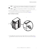
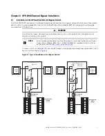
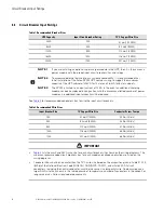
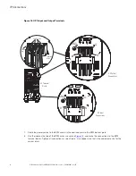
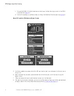
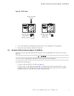
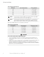
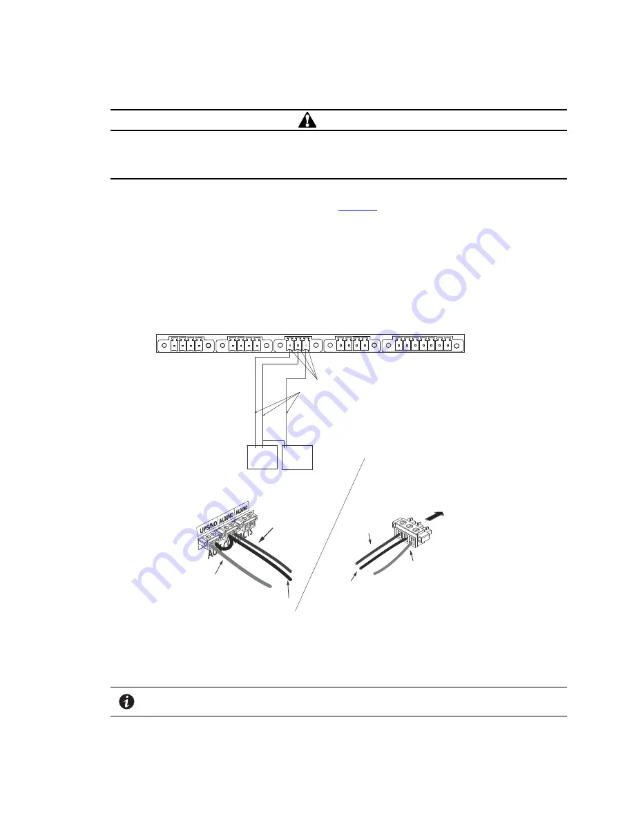
CAUTION
The auxiliary contacts must be wired to the BPM from the UPS for proper functionality. These auxiliary contacts
signal the UPS to go to Internal Bypass mode to provide a synchronized transfer. Failure to wire the auxiliary
contacts can be dangerous and result in system failure.
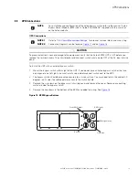
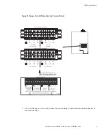
1.
Route the maintenance bypass signal wires in a conduit from the bypass module to the communication
signal terminal (CN13) on the rear of the UPS ( See
). For conduit requirements consult your local
electrical code.
2.
Place the signal wires through the proper conduit or grommet to the terminal block in the BPM.
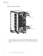
Figure 20. UPS Input Control Signal Wiring for Maintenance Bypass
AUX NO
CONTACT
NO
CONTACT
ON UPS
(white wire)
BYPASS
NEUTRAL
(black wire)
FORCED
BYPASS IN
(red wire)
External CAN to EBM
(
CN4)
Maintenance Bypass
(
CN13)
EPO
(
CN7)
3 2 1
4 3 2 1
4 3 2 1
4 3 2 1
7 6 5 4 3 2 1
Input signal
wires
ROO and On Generator
(
CN6)
Building Input
(
CN5)
Bypass Module
Terminal
BYPASS
NEUTRAL
(black wire)
FORCED
BYPASS IN
(red wire)
FORCED
BYPASS IN
(red wire)
BYPASS
NEUTRAL
(black wire)
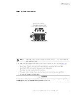
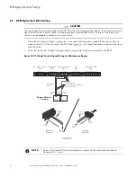
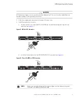
Attach supplied
wire connectors to input wires
and plug into UPS
BPM Signal
Terminals
ON UPS
(white wire)
ON UPS
(white wire)
(Install conduit
over signal wires)
UPS Signal
Terminals
NOTE
Do not strain relieve EPO or external bypass wiring with the same cable tie used for
Generator “On” wires.
Содержание 9PXM
Страница 1: ...p n P 164000669 Revision 09 Eaton 9PXM UPS 4 20kVA Users Guide Eaton 9PXM UPS ...
Страница 4: ......
Страница 8: ...viii 4 20kVA Users Guide P 164000669 4 20kVA Users Guide P 164000669 Rev 09 Table of Contents ...
Страница 12: ...xii 4 20kVA Users Guide P 164000669 4 20kVA Users Guide P 164000669 Rev 09 List of Figures ...
Страница 14: ...xiv 4 20kVA Users Guide P 164000669 4 20kVA Users Guide P 164000669 Rev 09 List of Tables ...
Страница 22: ...8 4 20kVA Users Guide P 164000669 4 20kVA Users Guide P 164000669 Rev 09 Physical Features ...
Страница 74: ...60 4 20kVA Users Guide P 164000669 4 20kVA Users Guide P 164000669 Rev 09 Connected Battery Cabinet Option ...
Страница 84: ...70 4 20kVA Users Guide P 164000669 4 20kVA Users Guide P 164000669 Rev 09 Initial Startup Parameters ...
Страница 110: ...96 4 20kVA Users Guide P 164000669 4 20kVA Users Guide P 164000669 Rev 09 Communication Slots ...
Страница 114: ...100 4 20kVA Users Guide P 164000669 4 20kVA Users Guide P 164000669 Rev 09 UPS Firmware Upgrade ...
Страница 120: ...106 4 20kVA Users Guide P 164000669 4 20kVA Users Guide P 164000669 Rev 09 Receptacle Circuit Breaker Ratings ...
Страница 126: ...112 4 20kVA Users Guide P 164000669 4 20kVA Users Guide P 164000669 Rev 09 Service and Support ...
Страница 130: ...P 16400066909 P 164000669 09 ...