


Eaton 93PM Integrated Accessory Cabinet-Tie (50 kW and 100 kW IAC-T) Installation and Operation Manual P-164000371—Rev 05
49
4.
If wiring the IAC-T input power terminals using the inter-cabinet wiring access pass-through (line-up-and-
match configurations), proceed to
; if wiring the IAC-T input power terminals using the bottom entry
access, proceed to
; if wiring the IAC-T input power terminals using the top entry access, proceed
to
.
5.
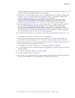
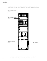
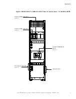
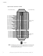
Pass-through Wiring.
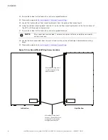
Route the IAC-T MOB input cables (phase A, B, and C and Ground) from the UPS
cabinets through the bottom UPS and IAC-T inter-cabinet wiring access pass-through to the IAC-T MOB
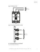
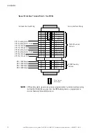
input terminals. See
for IAC-T wiring access information and
, or
for IAC-T terminal locations. See paragraph
IAC-T Power Wiring Preparation
, or
for IAC-T wiring and termination requirements. Refer to the applicable Eaton 93PM UPS Installation
and Operation manual, listed in paragraph
, for the UPS terminal locations and
termination requirements.
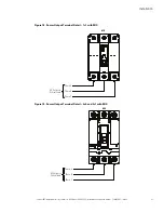
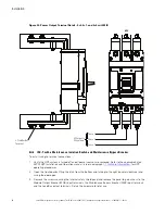
6.
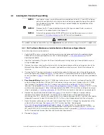
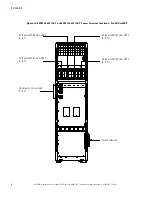
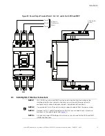
Remove the top or bottom conduit plate (see
) from the IAC-T. Identify all input and output
conduit requirements and mark their location. Drill and punch all conduit holes in the conduit plate prior to
mounting on the IAC-T. Reinstall the conduit plate. Install conduit between the IAC-T and the critical load or
Integrated Accessory Cabinet-Distribution (IAC-D). Pull the wiring through conduit into the wiring area.
7.
Route the output cables (phase A, B, and C and Ground) from the IAC-T through the top or bottom of the
cabinet to the critical load. See
, or
for IAC-T terminal locations. See
paragraph
IAC-T Power Wiring Preparation
,
,
, or
for IAC-T wiring and
termination requirements. Refer to the
Eaton 93PM Integrated Accessory Cabinet-Distribution (50 kW, 100
kW, 150 kW, and 200 kW IAC-D) Installation and Operation Manual
, listed in paragraph
, for IAC-D conduit and terminal locations and termination requirements.
8.
Route the maintenance bypass input (phase A, B, and C, and Ground) through the top or bottom of the
IAC-T to the MBP terminals. See
, or
for IAC-T terminal locations. See
paragraph
IAC-T Power Wiring Preparation
,
,
, or
for IAC-T wiring and
termination requirements.
9.
Proceed to
10.
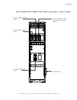
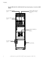
Bottom Entry Wiring.
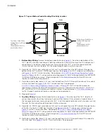
Remove the bottom conduit plate (see
) from the inside bottom of the
IAC-T. Identify all conduit requirements (both input and output) and mark their location. Drill and punch all
conduit holes in the bottom conduit plate prior to mounting on the IAC-T. Install the conduit plate and
install all conduit runs into the plate. Pull the wiring through conduit into the wiring area.
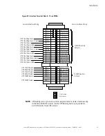
11. Route the IAC-T MOB input cables (phase A, B, and C and Ground) from the UPS cabinets through the
bottom of the IAC-T to the IAC-T MOB input terminals. See
for IAC-T wiring access information
and
,
, or
for IAC-T terminal locations. See paragraph
IAC-T Power Wiring Preparation
, or
for IAC-T wiring and termination
requirements. Refer to the applicable Eaton 93PM UPS Installation and Operation manual, listed in
paragraph
, for the UPS terminal locations and termination requirements.
12. Route the output cables (phase A, B, and C and Ground) from the IAC-T through the bottom of the cabinet
to the critical load. See
,
, or
for IAC-T terminal locations. See paragraph
IAC-T Power Wiring Preparation
, or
for IAC-T wiring and termination
requirements. Refer to the
Eaton 93PM Integrated Accessory Cabinet-Distribution (50 kW, 100 kW, 150
kW, and 200 kW IAC-D) Installation and Operation Manual
, listed in paragraph
for IAC-D conduit and terminal locations and termination requirements.
13. Route the maintenance bypass input (phase A, B, and C, and Ground) through the bottom of the IAC-T to
the MBP terminals. See
,
, or
for IAC-T terminal locations. See paragraph
IAC-T Power Wiring Preparation
, or
for IAC-T wiring and termination
requirements.
14. Proceed to
15.
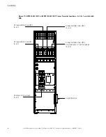
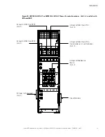
Top Entry Wiring.
Remove the top conduit plate (see
) from the top of the IAC-T. Identify all
conduit requirements (both input and output) and mark their location. Drill and punch all conduit holes in
Содержание 93PM IAC-T Series
Страница 98: ...P 16400037105 P 164000371 05 ...