

42
Eaton 93PM Integrated Accessory Cabinet-Tie (50 kW and 100 kW IAC-T) Installation and Operation Manual P-164000371—Rev 05
1.
Verify the UPS system is turned off and all power sources are removed. Refer to the applicable Eaton
93PM UPS Installation and Operation manual, listed in paragraph
, for UPS
operating procedures.
2.
Open the front door by lifting the latch from the bottom and turning to the right (counterclockwise) and
swing the door open.
3.
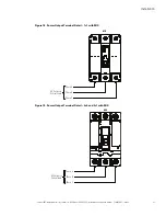
Remove the screws securing the internal safety shield panel and remove the panel to gain access to the
Module Output Breaker (MOB) input terminals and the Maintenance Isolation Switch (MIS) output
terminals. Retain the hardware for later use.
4.
If wiring the IAC-T input power terminals using the inter-cabinet wiring access pass-through (line-up-and-
match configurations), proceed to
; if wiring the IAC-T input power terminals using the bottom entry
access, proceed to
; if wiring the IAC-T input power terminals using the top entry access, proceed to
.
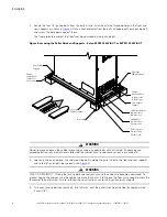
5.
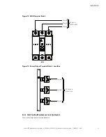
Pass-through Wiring.
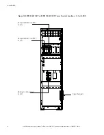
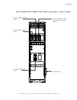
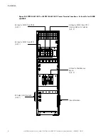
Route the IAC-T MOB input cables (phase A, B, and C and Ground) from the UPS
cabinets through the bottom UPS and IAC-T inter-cabinet wiring access pass-through to the IAC-T MOB
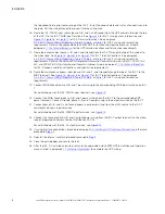
input terminals. See
for IAC-T wiring access information and
,
, or
for IAC-T terminal locations. See paragraph
IAC-T Power Wiring Preparation
,
,
, or
for IAC-T wiring and termination requirements. Refer to the applicable Eaton 93PM UPS Installation
and Operation manual, listed in paragraph
, for the UPS terminal locations and
termination requirements.
6.
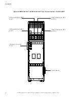
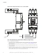
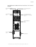
Remove the top or bottom conduit plate (see
) from the IAC-T. Identify all output conduit
requirements and mark their location. Drill and punch all conduit holes in the conduit plate prior to
mounting on the IAC-T. Reinstall the conduit plate. Install conduit between the IAC-T and the critical load or
Integrated Accessory Cabinet-Distribution (IAC-D). Pull the wiring through conduit into the wiring area.
7.
Route the output cables (phase A, B, and C and Ground) from the IAC-T through the top or bottom of the
cabinet to the critical load. See
, or
for IAC-T terminal locations. See
paragraph
IAC-T Power Wiring Preparation
, or
for IAC-T wiring and
termination requirements. Refer to the
Eaton 93PM Integrated Accessory Cabinet-Distribution (50 kW, 100
kW, 150 kW, and 200 kW IAC-D) Installation and Operation Manual
, listed in paragraph
, for IAC-D conduit and terminal locations and termination requirements.
8.
Proceed to
.
9.
Bottom Entry Wiring.
Remove the bottom conduit plate (see
) from the inside bottom of the
IAC-T. Identify all conduit requirements (both input and output) and mark their location. Drill and punch all
conduit holes in the bottom conduit plate prior to mounting on the IAC-T. Install the conduit plate and
install all conduit runs into the plate. Pull the wiring through conduit into the wiring area.
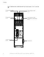
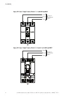
10. Route the IAC-T MOB input cables (phase A, B, and C and Ground) from the UPS cabinets through the
bottom of the IAC-T to the IAC-T MOB input terminals. See
for IAC-T wiring access information
and
,
, or
for IAC-T terminal locations. See paragraph
IAC-T Power Wiring Preparation
,
,
, or
for IAC-T wiring and termination
requirements. Refer to the applicable Eaton 93PM UPS Installation and Operation manual, listed in
paragraph
, for the UPS terminal locations and termination requirements.
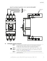
11. Route the output cables (phase A, B, and C and Ground) from the IAC-T through the bottom of the cabinet
to the critical load. See
, or
for IAC-T terminal locations. See paragraph
IAC-T Power Wiring Preparation
,
,
, or
for IAC-T wiring and termination
requirements. Refer to the
Eaton 93PM Integrated Accessory Cabinet-Distribution (50 kW, 100 kW, 150
kW, and 200 kW IAC-D) Installation and Operation Manual
, listed in paragraph
,
for IAC-D conduit and terminal locations and termination requirements.
12. Proceed to
.
13.
Top Entry Wiring.
Remove the top conduit plate (see
) from the top of the IAC-T. Identify all
conduit requirements (both input and output) and mark their location. Drill and punch all conduit holes in
Содержание 93PM IAC-T Series
Страница 98: ...P 16400037105 P 164000371 05 ...