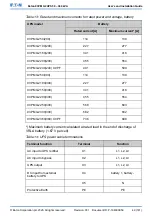


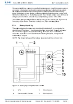


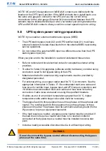


C
External battery breaker
7
Aux contact return
1
BAT_shut_DET
8
Aux contact
2
GND
9
Shunt trip coil -
3
Aux contact return
10
Shunt trip coil +
4
Aux contact
5.4
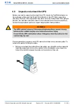
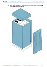
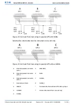
Installing UPS external battery cabinet and battery
power cabling
There is a vast offering of different Eaton external battery cabinets available for
the 93PM-G2 UPSs. Please refer to the three-phase accessories offering for
further details. See a separate manual for instructions on how to install Eaton
external battery cabinets.
NOTE: Do not connect battery strings with different battery quantity and voltage
in parallel.
Cable entry to the UPS is always on the top or the bottom of the cabinet.
NOTE: If batteries are wired outside the cabinets, follow the installation
instructions given in Section 4.4.3 UPS system power wiring preparations.
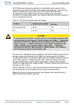
5.5
Install a remote EPO switch
You can use a remote EPO switch in case of an emergency to shut down the
UPS and remove power to the critical load from a location away from where the
UPS is installed.
EPO is connected to the UPS's top front panel, on connector EPO.
Figure
19: Connections of the EPO switch
shows the NO and NC connections of the
EPO switch.
EPO connector (front view):
•
A = Normally open
•
B = Normally closed
© Eaton Corporation plc 2020. All rights reserved.
Revision: 001
Document ID: P-164000956
63 (141)
Eaton 93PM G2 UPS 50 – 360 kVA
User’s and Installation Guide