


6
Communication interfaces
6.1
About communication interfaces
This section describes the communication features of the Eaton 93PM G2 UPS.
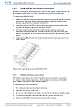
CAUTION
All the communication interfaces are SELV circuits. When connecting to
other equipment, make sure that you maintain this characteristic.
The UPS has the following communication interfaces:
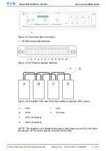
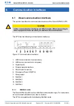
Figure 27: Communication interfaces
1.
USB host (connection to accessories)
2.
USB device (connection to computer)
3.
Signal inputs
4.
External parallel interface
5.
RS-232 port for service
6.
Emergency Power Off (EPO)
7.
Relay output
8.
MiniSlot 1
9.
MiniSlot 2
10. MiniSlot 3
11. MiniSlot 4
6.1.1
MiniSlot cards
The Eaton 93PM G2 UPS has four MiniSlot communication bays. For instructions
on how to install a MiniSlot card, refer to
Section
.
The UPS is compatible with the following MiniSlot cards:
© Eaton Corporation plc 2020. All rights reserved.
Revision: 001
Document ID: P-164000956
80 (141)
Eaton 93PM G2 UPS 50 – 360 kVA
User’s and Installation Guide