


Sync Control for Eaton 9395P and 93PM
20
User’s and Installation Guide
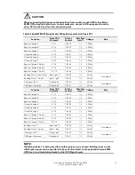
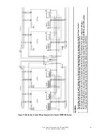
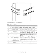
Table 3-5 Eaton 93PM UPS System Control Wiring Interconnections for Parallel Systems (Distributed
Bypass)
Function
From UPS
System A
To Sync
Control
Wire Size
[mm
2
]
Voltage
Note
Bypass Voltage A
System A
(1
Bypass Phase A
TB1-78
1,5
400Vac
Bypass Voltage B
System A
(1
Bypass Phase B
TB1-79
1,5
400Vac
Bypass Voltage C
System A
(1
Bypass Phase C
TB1-80
1,5
400Vac
Output Voltage A
System A
(2
Output Phase A
TB1-81
1,5
400Vac
Output Voltage B
System A
(2
Output Phase B
TB1-82
1,5
400Vac
Output Voltage C
System A
(2
Output Phase C
TB1-83
1,5
400Vac
Bypass Voltage A Return
X11-8
(3
TB1-84
1,5
400Vac
Bypass Voltage B Return
X11-9
(3
TB1-85
1,5
400Vac
Bypass Voltage C Return
X11-10
(3
TB1-86
1,5
400Vac
Building Alarm 1
(4
Input1 pin10
(3
TB1-54
1,5
24Vdc
Twisted pair
Building Alarm 1 Return
Input1 pin9
(3
TB1-55
1,5
24Vdc
On Bypass (N.O.)
Output pin2
(3
TB1-52
1,5
24Vdc
Twisted pair
On Bypass Common
Output pin3
(3
TB1-51
1,5
24Vdc
Function
From UPS
System B
To Sync
Control
Wire Size
[mm
2
]
Voltage
Note
Bypass Voltage A
System B
(1
Bypass Phase A
TB1-87
1,5
400Vac
Bypass Voltage B
System B
(1
Bypass Phase B
TB1-88
1,5
400Vac
Bypass Voltage C
System B
(1
Bypass Phase C
TB1-89
1,5
400Vac
Output Voltage A
System B
(2
Output Phase A
TB1-90
1,5
400Vac
Output Voltage B
System B
(2
Output Phase B
TB1-91
1,5
400Vac
Output Voltage C
System B
(2
Output Phase C
TB1-92
1,5
400Vac
Bypass Voltage A Return
X11-8
(3
TB1-93
1,5
400Vac
Bypass Voltage B Return
X11-9
(3
TB1-94
1,5
400Vac
Bypass Voltage C Return
X11-10
(3
TB1-95
1,5
400Vac
Building Alarm 1
(4
Input1 pin10
(3
TB1-56
1,5
24Vdc
Twisted pair
Building Alarm 1 Return
Input1 pin9
(3
TB1-57
1,5
24Vdc
On Bypass (N.O.)
Output pin2
(3
TB1-53
1,5
24Vdc
Twisted pair
On Bypass Common
Output pin3
(3
TB1-51
1,5
24Vdc
NOTES:
1.
Voltage taken from UPS System input switchgear through N.O. aux contacts of UPS
input (bypass) feeders.
2.
Voltage taken from UPS System output switchgear, system common output.
3.
Connection point in each UPS of a parallel system. Signals can be daisy-chained from
one UPS to next.
4.
If Building Alarm 1 is being used for another purpose, any unused building alarm on
the UPS Signal Inputs can be used for the Sync Control. Refer to the applicable Eaton
93PM UPS User’s and Installation Guide for the UPS Signal Inputs.