


66
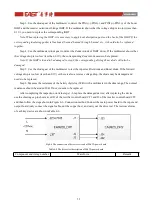
and then follow the steps shown in Figure 6-16. Connection method for drive test. The test waveforms of each key
device are shown in Table 6-16.
Fig.6-16 The connection of drive test circuit of 30kVA IP/OP board
Table 6-16 The driver test description of 30kVA IP/OP board
If it is found that the individual IGBT drive wareform is abnormal during the drive test, please re-check
whether the device is replaced, and check whether the corresponding drive module is damaged.
6.3 Maintenance of Bypass board
6.3.1 Maintenance of 10kVA bypass board
The 10kVA bypass board mainly includes bypass output circuit and output current sampling circuit. Tthe
frogile component of bypass board is bypass SCR, which are shown in Table 6-17, and its position in the board is
shown in Figure 6-17.
Table 6-17 The frogile components of 10kVA bypass board
Components
Tag Number
Specifications
Alternative
specification
Bypass SCR
Q1,Q2,Q3,Q4,Q5,Q6
VS-40TPS12A-M3
BT155W-1200T
Component and its tag number
Waveform
Remark
Charger IGBT
Q19,Q20
High level
+15V±1V
;
Low level
-8V±1V
;
Frequency
40KHz
;
Содержание EA990G5
Страница 4: ...7 1 Boards installation 72 7 2 Preparation before power on 72 7 3 Power on and testing 72...
Страница 9: ...5 Fig 2 5 The rear pannel of 30kVA UPS Tower Fig 2 6 The rear pannel of 10kVA 15kVA 20kVA UPS Rack...
Страница 43: ...39 Fig 5 9 The left side board of 15kVA standard model Tower Fig 5 10 The board of 15kVA model Rack...
Страница 48: ...44 Fig 5 19 The left side board of 30kVA standard model Tower...