Earthcore Industries
02/2021
Isokern Maximus Linear Series See-Thru Gas Fireplace
41
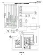
FIGURE 37
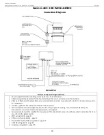
MFD Wiring
Wire that actuator for 2 wire/ 2 position operation as shown in
Figure 37
(120 VAC) and
Figure 38
(24
VAC) below. The actuator should be set for clockwise (CW) rotation and should fail to 90° (MFD will
open). Verify settings of the actuator before wiring.
Damper Actuator
Wiring Notes
The damper actuator will have a chord with 2 wires- black insulation wire and white
insulation wire. This chord supplies power for damper open / close operation
•
The black insulation wire is
L1
power -connect to
terminal 15
of ADC 100
•
The white insulation wire is
Neutra
l –
DOES NOT CONNECT TO ADC 100
- must
connect to any neutral wire that traces back to the circuit breaker box neutral
bus bar
The damper actuator will have a chord with 3 wires. These wires provide an
electrical signal that indicates the damper position open / close
•
purple insulation labeled
S1
will connect to
terminal 16
of ADC 100
•
red insulation wire labeled
S2 NOT USED,
cap this wire
•
white insulation wire labeled
S3
will connect to
terminal 17
of ADC 100
Enervex RS FAN Wiring
All electrical wiring must be in
compliance with the local codes or
in their absence, with the National
Electric Code, NFPA 70 — latest edition.
If an external electrical source is utilized,
system must be electrically grounded in
accordance with requirements of the
authority having jurisdiction or, in the
absence of such requirements, with the
National Electrical Code NFPA 70 —
latest edition.
Power requirements for the system
depends on the fan size. Electrical
requirements are:
The chimney fans have a split capacitor motor with
infinitely variable speed.
The fan speed control supplied is rated 1 x 120 V/60
Hz and 5 Amps. It has an adjustable low voltage set
point of min. 65 V +/- 5 V. (
Figure 39
)
RS Fan Wiring Notes
•
N
- white insulated wire connects
terminal 5
of ADC 100 positive side of
capacitor, black insulation wire (in
capacitor box) and white wire from fan
motor (in capacitor box)
•
L1
- black insulated wire connects
terminal 4
of ADC 100 to A terminal of
Fan Speed Control rheostat switch
•
B terminal of Fan Speed Control
rheostat connects to black insulated
wire from fan (in capacitor box)
•
RS012
1 x 120 V/60 Hz
1.2 Amps
•
RS014
1 x 120 V/60 Hz
1.4 Amps
•
RS016
1 x 120 V/60 Hz
3.9 Amps
If any of the original wire supplied with the
!
insulation may melt or degrade, exposing bare
system must be replaced, use similar wire
of the same temperature rating. Otherwise,
wire.
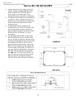
FIGURE 39
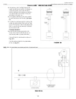
FIGURE 38


