background image


_______________________________________________________________________________________________________________________________ 

European Safety Systems Ltd.

   Impress House, Mansell Road, Acton, London W3 7QH           [email protected]                 Tel: +44 (0)20 8743 8880 

                                                                                                                                                             www.e2s.com                Fax: +44 (0)20 8740 4200 
Document No. IS 4601      Issue G                   13-01-20                       

Sheet 1 of  6


INSTRUCTION MANUAL 

IS-L101L 

Intrinsically Safe LED Beacon


1.  INTRODUCTION 

The  IS-L101L  is  an  ATEX  and  IECEx  certified  intrinsically 

safe  beacon  which  will  produce  a  visual  warning  in  a 

hazardous area. Red, Amber, Green and Blue output models 

are available. 


The beacon has been designed and certified to work alone or 

in  conjunction  with  a  European  Safety  Systems  IS-A105N 

intrinsically safe sounder. The beacon may be powered from 

the same intrinsically safe circuit as the IS-A105N intrinsically 

safe sounder, allowing  a  combined  audible  and  visual  alarm 

to  be  constructed.  The  IS-L101L  beacon  also  contains  an 

alarm  accept  facility  which  allows  an  operator  to  silence  the 

sounder  for  a  predetermined  time  while  leaving  the  beacon 

flashing or the sounder can be silenced after a predetermined 

time period has elapsed. 
 

When  using  the  IS-L101L  beacon  with  an  IS-A105N 

sounder,  the  Special  Conditions  for  Safe  Use  in  the 

sounder certificate, Sira 04ATEX2301X must also be met. 


2. DESCRIPTION 

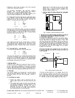
Fig 1 shows a simplified block diagram of a IS-L101L beacon. 

The  device  will  start  to  flash  when  power  is  applied  to 

ter and -. Terminals S+ and S- are for the connection 

of  an  optional  IS-A105N  sounder  which  will  operate 

immediately  power  is  applied  to  the  beacon.      The  sounder 

may  be  silenced  for  a  predetermined  time  by  momentarily 

connecting the Ac.Sw terminals together.  The silence time is 

set  by  DIP  switches  1  to  4  for  time  periods  between  5 

seconds  and  2  hours. 

By  setting  DIP  switch  5  to  ON  the 

sounder  will  silence  after  a  preset  time,  but  sound  will 

not  be  restored  until  the  power  to  the  beacon  has  been 

removed  and  restored.

  Setting  DIP  switch  6  to  ON  will 

provide  a  1  second  reminder  beep  tone  sound  while  the 

sounder  is  silenced.  The  interval  between  the  1  second 

reminder  beep  is  dependent  on  the  timing  setting  for  the 

silence  period,  (switches  1  to  4)  see  page  5. 

When the 

beacon is operated alone, without a sounder connected, 

all of the DIP switches should be set to the OFF position. 


When used alone, i.e. without a sounder connected, two flash 

frequencies  may  be  selected.    With  the  Ac.Sw  terminals 

disconnected  the  beacon  will  produce  two  flashes  in  quick 

succession  once  per  second.      The  flash  frequency  can  be 

doubled  by  permanently  connecting  the  Ac.Sw  terminals 

together.  


When used with a sounder, the beacon produces two flashes 

in quick succession once per second.   When the sounder is 

silenced the flash frequency is automatically doubled. 


3. SUPPLY VOLTAGE 

The  IS-L101L  beacon  has  been  designed  to  operate  in  a 

hazardous  area  via  28V  660mA  1.2W  ATEX  and  IECEx 

certified  Zener  Barriers  or  Galvanic  Isolators.  The  beacon 

may be tested or used in safe areas without a Zener Barrier 

or  Galvanic  Isolator,  but  at  supply  voltages  above  16V  the 

internal  current  limit  will  function  and  the  brightness  may  be 

reduced.    The beacon  should not  be continuously  operated 

without a barrier or isolator with a supply voltage greater than 

16V.  


Current Limit

Sounder Silence and 
Timing Circuits

Connection to 
Optional IS-A105N 
Sounder

S+

S-

+

-

Power 
Supply

16V

LED's

Accept 
Switch


Fig 1 Simplified block diagram 


4. INTRINSIC SAFETY CERTIFICATION 


4.1 ATEX certificate 

The IS-L101L beacon complies with the following standards:-  
 
EN IEC 60079-0:2018 
EN60079-11:2012 


The  EC-Type  Examination  Certificate  SIRA  04ATEX2302X 
has  been  issued  by  the  Notified  Body  Sira.  This  confirms 
compliance  with  the  European  ATEX  Directive  94/9/EC  for 
Group  II,  Category  1G  equipment.    The  beacon  carries  the 
Community Mark and subject to local codes of practice, may 
be  installed  in  any  of  the  EEA  member  countries.  This 
instruction  sheet  describes  installations  which  conform  to 
EN60079:Part14:2008  Electrical  Installation  in  Hazardous 

The IS-L101 beacon is CE marked for 

compliance with the European Explosive 

Atmospheres Directive 94/9/EC and the 

European EMC Directive 89/336/EEC 

II 1G        Ex ia IIC T4 Ga (-40ºC <= Ta <= +60ºC) 

Содержание IS-L101L

Страница 1: ...d reminder beep tone sound while the sounder is silenced The interval between the 1 second reminder beep is dependent on the timing setting for the silence period switches 1 to 4 see page 5 When the beacon is operated alone without a sounder connected all of the DIP switches should be set to the OFF position When used alone i e without a sounder connected two flash frequencies may be selected With...

Страница 2: ...FE USE as stated on the IS L101L EC Type Examination Certificate SIRA 04ATEX2302X The enclosure is non conducting and may generate an ignition capable level of electrosatic charges under certain extreme conditions The user should ensure that the equipment is not installed in a location where it may be subjected to external conditions that might cause a build up of electrostatic charges on non cond...

Страница 3: ...uitable for installation in an exterior location if an appropriate sealed cable entry is used 5 1 Mounting The IS L101L beacon may be secured to any flat surface using the two 6mm diameter fixing holes The lens should be aimed towards the area where maximum visibility is required 5 2 Installation procedure a Remove the beacon lens by unscrewing the two captive screws and pull the lens away from th...

Страница 4: ...suitable for the environmental conditions to which it is subjected located within the same hazardous area as the beacon see section 4 5 In order that the beacon continues to produce a reasonable light output level when used in conjunction with an IS A105N sounder the power supply voltage to the barrier should be maintained at a minimum of 18V 7 ELECTRICAL SYSTEM DESIGN FOR INSTALLATION IN HAZARDOU...

Страница 5: ...not been damaged Frequency of inspection depends upon environmental conditions but initially we recommend that this should be done annually No attempt should be made to repair a faulty IS L101L beacon Suspect beacons must be returned to European Safety Systems Ltd or to your local agent for repair 11 GUARANTEE Beacons which fail within the guarantee period should be returned to European Safety Sys...

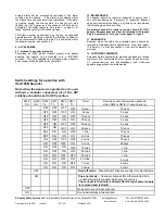
Страница 6: ...of the equipment should be done only with a damp cloth The IS L101L beacons are marked with the certification requirements for the ATEX and IECEx approvals e2S european safety systems ltd London W3 7QH UK www e2s com WARNING TO AVOID A POSSIBLE ELECTROSTATIC CHARGE ONLY CLEAN WITH A DAMP CLOTH IS L101L Beacon II 1G 2813 SIRA 04ATEX2302X Year Serial No 09 1000001 IECEx SIR 04 0039X Ui 28V Ii 660mA ...

Страница 7: ...ngle channel barrier having parameters less than or equal to those quoted and for which the output is non ignition capable for the Class Division or Zone and Group of use 7 The IS L101L Beacon enclosure has an ingress protection rating of IP 66 If supplied without cable entry devices then metallic or plastic cable glands or conduit hubs shall be fitted that provide the required environmental prote...

Страница 8: ...or equal to those quoted and for which the output is non ignition capable for the Class Division or Zone and Group of use 6 The IS L101L Beacon enclosure has an ingress protection rating of IP 66 If supplied without cable entry devices then metallic or plastic cable glands or conduit hubs shall be fitted that provide the required environmental protection 7 To prevent ignition of flammable or combu...

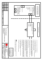
Страница 9: ...onents may impair safety 10 C cable capacitance of cable connecting the shunt zener diode barrier to the beacon capacitance of the cable connecting the sounder to the beacon 11 The total capacitance connected to terminals of the beacon plus the total capacitance connected to terminals of the sounder i e C cable plus any other capacitance shall not exceed 83nF 12 L cable loop inductance of cable co...

Страница 10: ...e sounder to the beacon 10 The total capacitance connected to terminals of the beacon plus the total capacitance connected to terminals of the sounder i e C cable plus any other capacitance shall not exceed 83nF 11 L cable loop inductance of cable connecting the galvanically isolated supply to the beacon loop inductance of cable connecting the sounder to the beacon Note CAUTION Bonding between con...

Отзывы: