__________________________________________________________________________________________________________________
European Safety Systems Ltd.
Impress House, Mansell Road, Acton, London W3 7QH [email protected] Tel: +44 (0)20 8743 8880
www.e2s.com Fax: +44 (0)20 8740 4200
Document No. IS4201 Issue: G 19-06-07 Sheet 1 of 3
INSTRUCTION & SERVICE MANUAL
E2xS112UL ALARM HORN SOUNDERS
For Use In Hazardous Locations
•
45 Tones 3 stage Alarm Horn Sounder
•
Automatic Synchronisation
•
Volume control
•
Type 4 / 4X / 13
•
Operating Temperature Range
-20ºC to +55ºC
7KA1
Unit Type No.
E2xS112UL
Input Voltages:
DC Units
10-30V or 48V
AC Units
120V or 230V 50/60Hz
Max. Operating Temperature / Code at +55ºC Ambient
Hazardous Location
Temperature Code
Class I, Division 2, Groups A, B, C, D
T3C (160ºC)
Class II, Division 2, Groups F and G
T6 (85ºC)
Class III, Divisions 1 and 2
T6 (85ºC)
Max. Operating Temperature / Code at +40ºC Ambient
Hazardous Location
Temperature Code
Class I, Division 2, Groups A, B, C, D
T4 (135ºC)
The equipment is suitable for use in the hazardous locations
listed above or non-hazardous locations only.
PRE-INSTALLATION
WARNING
-
Before the E2xS112UL sounder is installed the
required tone and output volume must be set.
Note the units
are factory set to tone 2 (800/1000Hz alternating at 2Hz) and
maximum output
. If necessary the unit should be connected to
a suitable power supply in a safe area to determine what tone
pattern and output level is required.
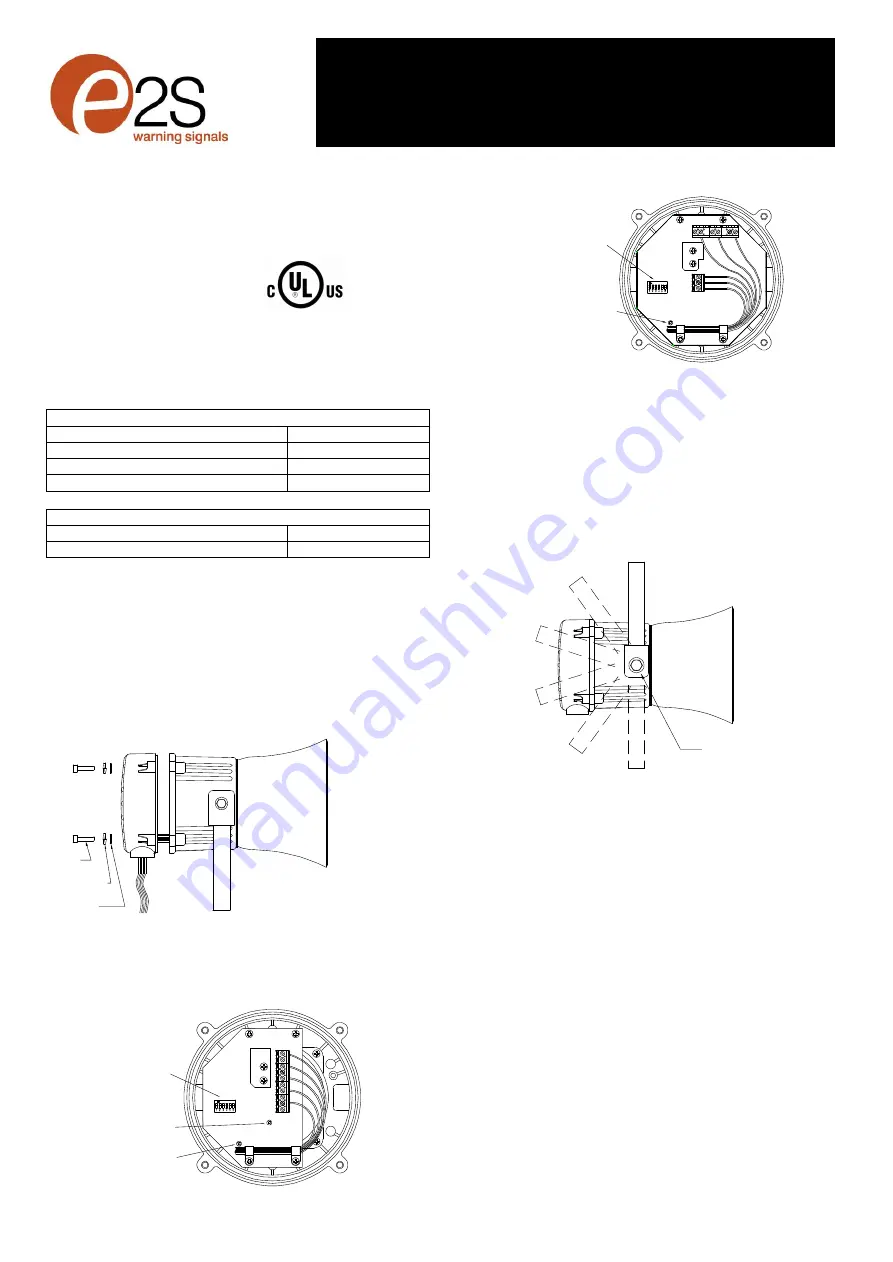
Flat Washer
Spring Washer
M4 Hex
Socket Screw
WARNING – DO NOT OPEN WHEN ENERGISED
CAUTION – DO NOT OPEN WHEN AN EXPLOSIVE GAS
OR DUST ATMOSPHERE IS PRESENT
WARNING -
EXPLOSION HAZARD - SUBSTITUTION OF
COMPONENTS MAY IMPAIR SUITABILITY
FOR CLASS I, II DIVISION 2.
MOUNTING
The E2xS112UL sounder must be mounted using the rotating
bracket as shown. If the cover has been removed to set the tone
or volume control ensure that it has been correctly replace
before the sounder is mounted.
18° Increments
Release nut to rotate
bracket.
WIRING INSTALLATION
The E2xS112UL sounder has one ½ NPT cable entry, the
blanking plug adjacent to the cable entry is permanently fixed
and must not be removed. The sounder is pre-wired with flying
leads which are colour coded and should be connected as
shown in the diagram below.
The conduit running from the supply to the sounder must
include an equipment grounding conductor that is at earth
potential to facilitate ground connection of the device. A number
of sounders can be connected in a chain to the same supply
using field installed wiring compartments that are appropriate for
the hazardous location, provided that the conductor at earth
potential can be readily connected to the ground lead on each
sounder in the chain.
WARNING - ALL ELECTRICAL WIRING MUST BE
INSTALLED IN ACCORDANCE TO THE
NATIONAL ELECTRICAL CODE
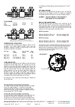
AC SOUNDERS
Black
Live
Violet
C
White
Neutral
Orange
S2
Green/Yellow
Ground
Yellow
S3
S
3
S
3
S
2
S
2
-
-
+
+
Tone Selection
DIP Switch
Volume Control
Potentiometer
24V Version
Volume Control
Potentiometer
48V Version
E2xS112UL DC Sounder
Tone Switch and Volume
Control Positions
G
G
E2xS112UL AC Sounder
Tone Switch and Volume
Control Positions
Tone Selection
DIP Switch
N N
E E
S
3
S
2
C
L L
Volume Control
Potentiometer


