background image


INSTRUCTION & SERVICE MANUAL


A112N AlertAlarm Sounder 


E2S Warning Signals Impress House, Mansell Road, Acton, London W3 7QH    [email protected]        e2s.com                                             D221

-

00

-

001

-

IS Issue 1  10/05/2021 


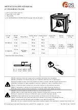
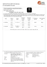
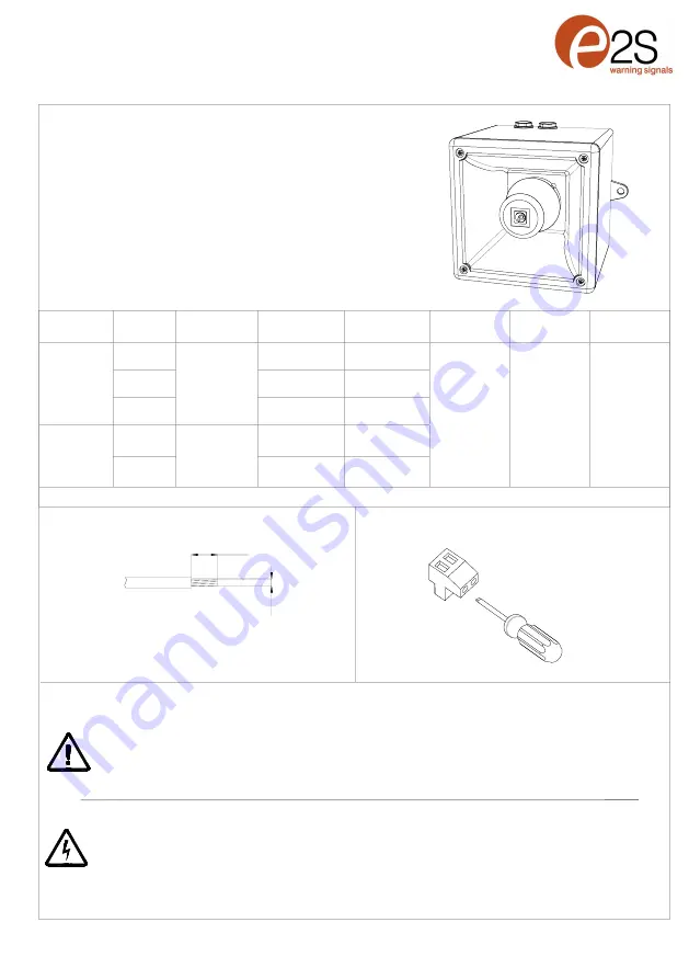
Unit Type 

Code


Nominal 

Voltage


Voltage Range


Nominal Current*


P1 


Nominal Current*


P2


Nominal SPL


P1 / P2


Max SPL


P1 / P2


Average SPL


P1 / P2


A112NDC024 


12 Vdc 


11.5

-

54Vdc


280mA 


376mA


113.7dB(A) / 

116.6dB(A) 

Tone 44 @ 1m


115dB(A) / 

118.4dB(A) 

Tone 4 @ 1m


110.8dB(A) / 

114.8dB(A) 


All Tones @ 

1m


24 Vdc 


225mA 


430mA


48 Vdc 


122mA 


223mA


A112NAC230


115 Vac 


100mA 


173mA


100

-

240Vac 

50/60Hz


230 Vac 


65mA 


 105mA


   *Nominal current at nominal voltage


• 

-

40°C to +66°C (104°F to 151°F)


• 

Type 4 / 4X / 3R / 13, IP66


• 

1.8Kg (3.96lb)


• 

CE, A112NXDC024 & A112NXDC048 CPR compliant, All units UL Listed


0.4Nm


5mm

0.5   2.5mm 

Attention

: Installation must be carried out by an electrician in compliance with the latest codes and regulations.


Attention

: L'installation doit être effectuée par un électricien conformément aux derniers codes et réglementations. 


Achtung

: Die Installation muss von einem Elektriker gemäß den neuesten Vorschriften und Bestimmungen durchgeführt werden.


Attenzione

: L'installazione deve essere eseguita da un elettricista in conformità con i codici e le normative più recenti.


Atención

: La instalación debe ser realizada por un electricista de acuerdo con los últimos códigos y regulaciones.


Atenção: 

A instalação deve ser realizada por um eletricista de acordo com os códigos e regulamentos mais recentes.


Внимание

установка должна выполняться электриком в соответствии с последними нормами и правилами

.


Attention

: Disconnect from power source before installation or service to prevent electric shock 


Attention

: Débranchez

-

le de la source d'alimentation avant l'installation ou l'entretien pour éviter tout choc électrique.


Achtung

: Vor Installation oder Wartung von der Stromquelle trennen, um einen Stromschlag zu vermeiden.


Attenzione

: scollegare dall'alimentazione prima dell'installazione o dell'assistenza per evitare scosse elettriche.


Atención

: desconéctelo de la fuente de alimentación antes de la instalación o el servicio para evitar descargas eléctricas.


Atenção: 

Desconecte da fonte de alimentação antes da instalação ou serviço para evitar choque elétrico 


Внимание

отключите от источника питания перед установкой или обслуживанием

чтобы предотвратить поражение электрическим током

.


AC: 1.0 –


2.5mm

/ AWG18 –


AWG12


DC: 0.2 –


2.5mm

/ AWG24 –


AWG12


Содержание A112N

Страница 1: ...Attenzione L installazione deve essere eseguita da un elettricista in conformità con i codici e le normative più recenti Atención La instalación debe ser realizada por un electricista de acuerdo con los últimos códigos y regulaciones Atenção A instalação deve ser realizada por um eletricista de acordo com os códigos e regulamentos mais recentes Внимание установка должна выполняться электриком в со...

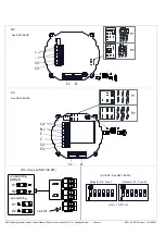
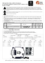
Страница 2: ...s com e2s com D221 00 001 IS Issue 1 10 05 2021 S2 S3 S2 S1 DC P1 P2 L N E C S2 S3 S2 S1 AC P1 P2 Default S2 Tone 1 Default S1 Tone 44 ON 1 OFF 0 AC DC See D221 95 001 DC Only see D221 06 001 H2 H1 ve switching Default H2 H1 ve switching Link W1 See D221 06 005 See D221 06 001 ...

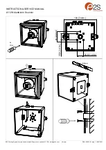
Страница 3: ...VICE MANUAL A112N AlertAlarm Sounder E2S Warning Signals Impress House Mansell Road Acton London W3 7QH sales e2s com e2s com D221 00 001 IS Issue 1 10 05 2021 4x 1Nm 190 7 48in 35 9 1 41in 35 9 1 41in 61 2 40in ø20mm ...

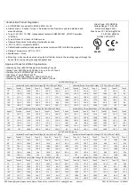
Страница 4: ... Output Min Voltage 11 5 Vdc LAFmax T dB A Angle Tone 44 Tone 8 Tone 2 Tone 21 Tone 31 Tone 5 Tone 44 Tone 8 Tone 2 Tone 21 Tone 31 Tone 5 15 103 3 103 7 103 1 103 3 103 2 91 5 101 101 5 100 9 101 100 3 89 4 45 103 4 104 8 104 2 101 6 96 3 99 4 101 5 102 7 101 8 99 6 94 3 97 4 75 109 1 110 4 109 7 109 6 108 3 103 2 107 1 108 2 107 4 107 7 105 9 101 4 105 109 9 110 2 109 6 109 7 108 6 103 107 7 108...

Страница 5: ...rating Current P1 Max Operat ing RMS P2 Nominal Operating Current P2 Max Operating RMS A112NDC024 12V dc 11 5 54V ac 280mA 280mA 376mA 430mA 24V dc 225mA 430mA 48V dc 122mA 223mA 115V ac 100 240V ac 50 60Hz 100mA 101mA A112NAC230 173mA 181mA 230V ac 65mA 105mA Max Operating current for worst case input voltage Nominal current at nominal voltage and Tone 44 The units have been tested and approved t...

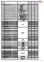
Страница 6: ... 0 0 0 1 0 1 0 0 0 0 1 1 0 0 0 1 1 1 0 0 0 0 0 0 1 0 0 1 0 0 1 0 0 0 1 0 1 0 0 1 1 0 1 0 0 0 0 1 1 0 0 1 0 1 1 0 0 0 1 1 1 0 0 1 1 1 1 0 0 0 0 0 0 1 0 1 0 0 0 1 0 0 1 0 0 1 0 1 1 0 0 1 0 0 0 1 0 1 0 1 0 1 0 1 0 0 1 1 0 1 0 1 1 1 0 1 0 1 1 0 1 1 0 0 0 1 1 1 0 0 1 1 1 1 0 0 0 0 0 0 1 0 1 0 0 0 1 1 1 0 0 0 1 0 0 1 0 0 1 1 0 1 0 0 1 0 1 1 0 0 1 1 1 1 0 0 1 0 0 0 1 0 1 0 1 0 1 0 1 1 0 1 1 0 1 0 1 1 1 0...

Страница 7: ...age Range Initial Peak Initial RMS A112NDC024 24V dc 11 5 54V dc P1 1455mA P2 1164mA P1 140mA P2 286mA A112NDC024 Sounder Directional Characteristics for Canadian Fire CAN ULC S525 at 10 feet Horizontal Axis Vertical Axis Angle OSPL Angle OSPL Angle OSPL Angle OSPL Ref 90 103 7 dB A Ref 90 103 7 dB A Ref 90 103 8 dB A Ref 90 103 78dB A 129 3 dB A 49 3 dB A 126 3 dB A 49 3 dB A 131 6 dB A 39 6 dB A...

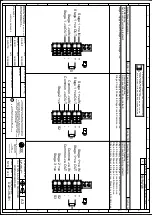
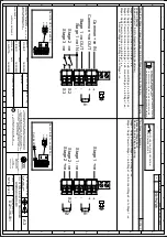
Страница 8: ...OTTS OF A112N A121 DC SOUNDER WIRING DIAGRAMS INTRODUCTION NTS 1 3 OPTIONAL LINE MONITORING RESISTOR CUSTOMER SUPPLIED 14V MAX SYSTEM 120Ω MIN 2W MIN OR 1KΩ MIN 0 5W MIN 28V MAX SYSTEM 470Ω MIN 2W MIN OR 2 4KΩ MIN 0 5W MIN RECOMMENDED MINIMUM VALUES R1 Stage 1 ve IN Stage 1 ve OUT Common ve IN Common ve OUT Stage 2 ve Stage 1 ve IN Stage 1 ve OUT Common ve IN Common ve OUT Stage 2 ve Stage 3 ve R1...

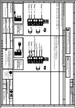
Страница 9: ... FOR STAGE OPERATION CUSTOMER SUPPLIED Stage 2 ve Common ve IN Common ve OUT Stage 1 ve OUT Stage 3 ve Stage 1 ve IN H2 H1 Stage 1 ve Stage 1 ve Stage 2 ve Stage 2 ve OF 2 3 R1 S2 S3 R1 S2 R2 OPTIONAL LINE MONITORING RESISTOR CUSTOMER SUPPLIED 14V MAX SYSTEM 120Ω MIN 2W MIN OR 1KΩ MIN 0 5W MIN 28V MAX SYSTEM 470Ω MIN 2W MIN OR 2 4KΩ MIN 0 5W MIN RECOMMENDED MINIMUM VALUES R1 Set H1 H2 to ve switch...

Страница 10: ... E 7 8 6 5 D C 1 3 4 2 A B D221 06 001 R S RAIT B ISARD R N POTTS A112N A121 DC SOUNDER WIRING DIAGRAMS NTS Stage 1 ve Stage 1 ve Stage 2 ve Stage 2 ve OF 3 3 R1 R1 S2 R2 Two Stage Configuration Config 4 Line Stage Monitoring Use suitable monitoring relays modules Not to be used for reverse polarity monitoring Stage 1 Apply Power to Stage 1 ve Stage 1 ve Stage 2 Apply Power to Stage 2 ve Stage 2 v...

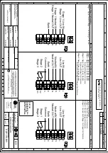
Страница 11: ... 3 4 2 A B D221 06 005 R S RAIT B ISARD R N POTTS OF A112N A121 AC WIRING DIAGRAMS NTS 1 SWITCHES FOR STAGE OPERATION CUSTOMER SUPPLIED 1 Earth Earth Stage 2 Stage 3 Common Live IN Live OUT Neutral IN Neutral OUT Earth Stage 1 Stage 2 Common N N L L E N N L L E C N N L L E C S2 S3 Live IN Live OUT Neutral IN Neutral OUT Stage 1 Live IN Stage 1 Live OUT Stage 1 Neutral IN Stage 1 Neutral OUT Single...

Страница 12: ...Page left Intentionally blank ...

Отзывы: