Technical
Bulletin
801 South Stevens • P.O. Box 179 • Spokane, WA 99210 • 509.624.6600 • 800.441.1309
97-0051-001 09/99
X-C 6250/X-C 6250 Pro Computers
Cradle Contact Cable Assembly Replacement Procedure
BellSouth Units Only
Tools required: #1 Philips screw driver
Procedure:
1. Ensure that power is disconnected from the cradle.
2. Remove the 14 screws that attach the cradle L base to the cradle case.
a) Remove the 6 screws from the back of the cradle.
b) Position the cradle so the bottom is face up and remove the 8 screws on the bottom.
c) Slide the L base toward the back of the cradle to allow the cradle PCB to clear the cradle case
3. Lift the L Base up slightly from the front (approximately 45 degrees) to allow access to the cable connection on the cradle
PCB.
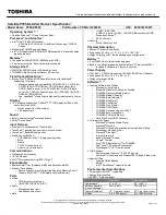
4. Grasp the top portion of the white connector (Cable to PCB [Male]) and press the locking tab to disconnect from the PCB.
Note: Considerations to prevent ESD damage to the cradle PCB components should be observed. Avoid contact with
the cradle PCB and components.
Cable to PCB
Connector(Male)
Locking Tab
Cable to PCB
Connector(Female)