Series UFC Ultrasonic Flowmeter Kit
Installation and Operating Instructions
Bulletin F-UFC
www.
.com
[email protected]
1.800.561.8187
Страница 1: ...Series UFC Ultrasonic Flowmeter Kit Installation and Operating Instructions Bulletin F UFC www com information itm com 1 800 561 8187 ...
Страница 2: ...tachment 11 2 3 3 Attaching the guide rail to the pipe 12 2 3 4 Fitting the transducers 12 2 3 5 Transducer attachment diagonal mode 15 3 Operating Procedures 17 3 1 Setting up the Instrument 18 3 1 1 Using the instrument for the first time 18 3 1 2 Changing the user language 19 3 1 3 Changing the date and time 19 3 2 Using the Quick Start Menu 19 3 3 Instrument Calibration 23 3 3 1 Adjusting the ...
Страница 3: ...et Up Automatic Timed Logging Mode 39 4 3 How to Download Logged Data 40 5 Maintenance Repair 42 5 1 Introduction 42 5 2 General care 42 5 3 Warranty Return 42 6 Troubleshooting 43 6 1 Overview 43 6 2 General Troubleshooting Procedure 44 6 3 Warning and Status Messages 45 6 4 Diagnostics Display 47 7 Options 49 7 1 Large Pipe Diameter Transducers 49 7 2 Transducer Holder Options 49 7 3 Extended Si...
Страница 4: ...or 24 Vdc Logging of Flows and Volume total Output to USB pen Volumetric flow rates are displayed in L h L min L sec gal min gal h USgals min USgals h Barrel h Barrel day m s m min m h Linear velocity is displayed in meters or feet per second When operating in the Flow Reading mode the total volumes both positive and negative are displayed up to a maximum 12 digit number The flowmeter can be used ...
Страница 5: ...lex mode Reflex mode double bounce Reflex mode triple bounce Diagonal mode This is the mode most commonly used The two transducers U D are attached to the pipe in line with each other and the signals passing between them are reflected by the opposite pipe wall The separation distance is calculated by the instrument in response to entered data concerning the pipe and fluid characteristics In this m...
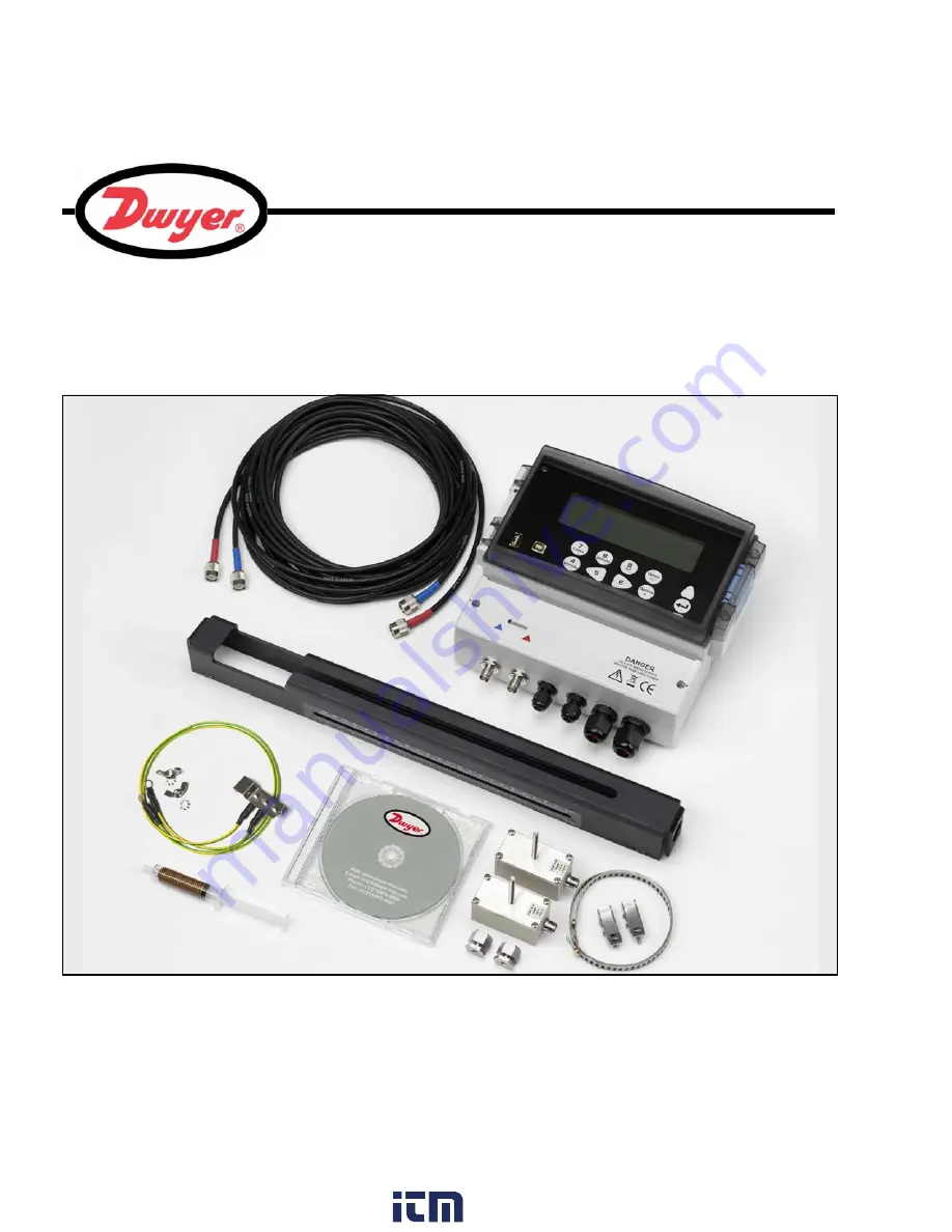
Страница 6: ...Instrument with backlit graphic display Transducer cables x2 16 5 feet 5 0m in length Transducers A ST x2 UFC A for use with pipes ranging 0 5 to 4 5 inches 13 to 115 mm Transducers B ST x2 UFC B for use with pipes ranging 2 to 79 Inches 50 to 2000 mm Transducer holder for use with A or B transducers Steel bands used to secure the transducer holder to the pipe Acoustic couplant applicator USB Memo...
Страница 7: ...cated on the bottom left hand of the instrument The silk screen above these connectors show a red and blue triangle and a direction of flow symbol For a positive flow reading it is important that the upstream transducer is connected to the RED socket and the downstream transducer to the BLUE one It is safe to connect or disconnect these cables while the instrument is switched on 4 to 20 mA Pulse a...
Страница 8: ...ey Some menus have more options than can be shown on the screen at the same time in which case the overflowed choices can be brought into view by continuing to scroll DOWN past the bottom visible item Menus generally loop around if you scroll beyond the first or last items If you select Exit on any menu it usually takes you back one level in the menu hierarchy but in some cases it may go directly ...
Страница 9: ...ion Power failure The instrument will automatically power up and become operational when the input power is applied In the event of a power failure the instrument s configuration parameters are stored in non volatile memory which then allows the instrument to return to normal operation immediately power is restored A real time clock RTC records the date and time of any power disruptions and time s...
Страница 10: ...rotected and connected via an identifiable isolator A 500 mA fuse is fitted internally in the instrument s input supply line WARNING LETHAL VOLTAGES You may be exposed to potentially lethal mains voltages when the terminal cover of this instrument is removed Always isolate the supply to this instrument before removing the terminal cover WARNING LETHAL VOLTAGES This instrument must be installed by ...
Страница 11: ...d drill and plug the two fixing points 5 Clear the site of any dust debris then mount the enclosure on the wall Figure 2 1 UFC Mounting and connection details GND TxD RxD mA mA PULSE PULSE AL1 AL1 AL2 AL2 IO1 IO2 IO3 IO4 IO5 IO6 IO7 IO8 IO9 IO10 IO11 IO12 F1 24V 230V AC L N E 4 5in 7 8in Screw Slot Keyhole Mounting Details The instrument should be securely wall mounted using the three fixing point...
Страница 12: ...on slot 1 Remove the terminal block cover 2 Route the control and monitoring cables through the two smaller cable glands 3 Cut the wires to length strip back the insulation by approximately 0 4in 10 mm and connect them to the required terminals identified in Figure 2 1 4 On completion tighten the cable glands to ensure the cables are held securely Power connections The UFC instrument can be powere...
Страница 13: ...10 x Diameter 20 x Diameter 45 Uniform Flow Profile Distorted Flow Profile Possible sludge Air Flow Transducer Holder 45 In many applications an even flow velocity profile over a full 360 is unattainable due to for example air turbulence at the top of the flow and possibly sludge in the bottom of the pipe Experience has shown that the most consistently accurate results are achieved when the transd...
Страница 14: ... of the flow readings may be affected Prepare the pipe by degreasing it and removing any loose material or flaking paint in order to obtain the best possible surface A smooth contact between the pipe surface and the face of the transducers is an important factor in achieving a good ultrasound signal strength and therefore maximum accuracy 2 3 2 Transducer attachment Figure 2 4 Transducer attachmen...
Страница 15: ... end of the pipe 2 3 4 Fitting the transducers 1 Tighten each transducer clamp clockwise until it is close to the top of the transducer Figure 2 6 This is necessary in order to prevent the acoustic couplant touching the pipe when the transducer is initially inserted into the guide rail as described below 2 Using the suppled syringe applicator apply a 0 1 inch bead of acoustic couplant to the base ...
Страница 16: ...e transducer is aligned with the 0 mark on the ruler scale Figure 2 10 7 Lower the transducer onto the pipe by turning the transducer clamp anti clockwise until it is finger tight do not use a spanner 8 Thread the upstream signal cable red through the left hand end of the mounting rail and connect it to the second transducer Figure 2 11 9 Following the method used to insert the downstream transduc...
Страница 17: ...nsure the transducer signal cables are correctly connected to the UFC instrument i e with the RED cable connected to the upstream transducer connector and the BLUE cable to the downstream transducer connector 13 In some cases particularly on large pipes using diagonal mode or pipes with a poor internal condition the signal from the sensors can be very noisy In order to improve sensor performance a...
Страница 18: ...n line A mark a position point Y 180 opposite point X 5 From point Y draw a three foot long line C perpendicular to A and parallel to the pipe axis This is shown as a dashed line in Figure 2 15 as it is on the rear of the pipe 6 Mark a position point Z on line C which is equal to the transducer separation distance noted in step 1 from point Y 7 Position and attach the upstream transducer holder to...
Страница 19: ...ng parallel either edge describes a circumference around the pipe that is perpendicular to the pipe axis Mark the chart paper exactly where it overlaps Then after removing the paper from the pipe fold the measured length in half keeping the edges parallel The fold line now marks a distance exactly half way around the pipe Put the paper back on the pipe and use the fold line to mark the opposite si...
Страница 20: ...measure totalized flows Paragraph 3 5 Operation with an Energy Meter Paragraph 3 7 Configure the interfaces Paragraph 3 4 Set date time Language Initial instrument setup Paragraph 3 1 Connect and take basic flow readings Paragraph 3 2 4 20mA ON OFF Paragraph 3 4 1 4 20mA Calibration Paragraph 3 4 1 Pulse ON OFF Paragraph 3 4 2 Pulse calibration Paragraph 3 4 2 Alarm outputs Paragraph 3 4 3 Data Lo...
Страница 21: ...U and press ENTER The SETUP INSTRUMENT screen should now be displayed 6 Select Set Date Time then press ENTER 7 A flashing cursor should appear under the first date number Enter the date sequence in dd mm yy order then press ENTER 8 Repeat this action to set the time 9 Select Exit then press ENTER to return to the MAIN MENU Note If you make a mistake when entering the data press the Delete key to ...
Страница 22: ...e applied when mounting the transducers on the pipe Before you can use the UFC system you need to obtain the following details this information is required when setting up the Quick Start menu The pipe outside diameter The pipe wall thickness and material The pipe lining thickness and material if any The type of fluid contained in the pipe being monitored The fluid temperature Entering the site da...
Страница 23: ...ropagation rate of the pipe wall material in meters sec Contact Dwyer if this is not known OUTSIDE DIAMETER DD MM YY HH MM SS Dimensions Inches Pipe outside diameter 6 50 PIPE WALL THICKNESS DD MM YY HH MM SS Dimensions Inches Pipe outside diameter 6 50 Pipe wall thickness 0 50 PIPE LINING THICKNESS DD MM YY HH MM SS Dimensions Inches Pipe outside diameter 6 50 Pipe wall thickness 0 50 Pipe lining...
Страница 24: ...Select Continue and press ENTER 15 The SENSOR SEPARATION screen now displays a summary of the entered parameters and informs you of the type of sensor to be used the mode of operation and the distance to set up between the sensors In this example it recommends type A ST A standard sensors operating in the Reflex mode spaced at 3 62 Inches apart Take a note of these details Key Point The above exam...
Страница 25: ...0 to disable the password control and gain access to any of the menus Note Once disabled the password control feature is re enabled if no keys are pressed for five minutes Attaching and connecting the transducers 21 Fit the designated sensors to the pipe using the transducer holder as described in Paragraph 2 3 2 The separation distance must be set to within 0 02 inches Taking a flow reading 22 On...
Страница 26: ...o set a minimum flow rate m s below which the instrument will indicate 0 The default setting is 0 1 m s but you may adjust this value if required 1 With the instrument operating in FLOW READING mode press the Options key to access the FLOW READING OPTIONS menu shown password required 2 Select Zero Cutoff m s and press ENTER 3 Enter the value for the Zero Cutoff e g 0 06 m s then press ENTER 4 Scro...
Страница 27: ...ween the UFC instrument and reference meters If the error is greater than 1 calibrate the UFC as detailed below Key Point In order to cancel any applied offset you must read the flow via Quick Start Any value that you trim out using the offset adjustment will be added subtracted from the flow reading across the whole range Key Point USE THIS FACILITY WITH CARE ONLY WHERE NECESSARY The instrument i...
Страница 28: ...ely if the reading is 1 low then decrease the calibration factor to 0 990 7 Press ENTER to apply the change 8 Select Roughness factor or Exit as required and press ENTER FLOW READING OPTION DD MM YY HH MM SS Data review Zero Cutoff m s 0 010 Set zero flow m s 0 000 Damping secs 10 Totalizer Run Reset Total Reset Total Calibration factor 1 000 Roughness factor 0 010 Alarm Settings Max Pulse Freq Hz...
Страница 29: ...ange 3 3 5 Adjusting the damping factor By averaging out the flow rate over several seconds the Damping factor can be used to smooth out rapid changes in flow rate to prevent wild fluctuations in the displayed flow value It has a range of 1 to 50 seconds with a default setting of 10 With the system running in FLOW READING mode Pipe Material Roughness Factor Pipe Material Roughness Factor Non ferro...
Страница 30: ...mping factor is set too high the value displayed may appear stable but might exhibit large step changes when the value is updated FLOW READING OPTION DD MM YY HH MM SS Data review Zero Cutoff m s 0 010 Set zero flow m s 0 000 Damping secs 10 Totalizer Run Reset Total Reset Total Calibration factor 1 000 Roughness factor 0 010 Alarm Settings Max Pulse Freq Hz 10 00 Flow at Max Frequency 200 00 Calc...
Страница 31: ...f the output ranges to turn it ON 5 Press ENTER to return to the 4 20mA OUTPUT screen 4 to 20 mA Signal calibration and ranging This procedure describes how to calibrate the 4 to 20 mA output and scale it to cover a defined flow rate range Signal calibration 6 Select Setup Instrument from the MAIN MENU then press ENTER to access the SETUP INSTRUMENT screen 7 Select Calibrate 4 20mA and press ENTER...
Страница 32: ...13 Select Flow at max output and press ENTER then enter a value of the flow rate that you want to associate with a 20 00 mA output 14 Select Flow at min output and press ENTER then enter a value of the flow rate that you want to associate with a 4 00 mA output This could be 0 15 Select Output mA for error and enter a value max of about 26 mA that you want the 4 to 20 mA output to produce in the ev...
Страница 33: ...ss ENTER 4 Enter the required value In the example shown a pulse is produced for every 10 gallons of flow Note The Vol per pulse can only be changed if the Pulse Output is Off 5 Select a Pulse width in ms to suit the particular application e g electro mechanical counter Refer to the manufacturer s data sheet for the minimum pulse width 6 Select Exit and press ENTER to return to the FLOW READING sc...
Страница 34: ...ctivate when a specified Volume is measured Activate if a signal error is detected either due to poor signal strength or complete signal loss Alarm Test mode Pulse Frequency output Alarm settings selection 1 To access the The ALARM SETTINGS menu select Alarm Settings from the FLOW READING OPTION menu and press ENTER 2 The ALARM SETTINGS screen should be displayed as shown below This screen shows t...
Страница 35: ... 999 99 to 3 999 999 999 99 This value will be in the units previous selected e g liters m3 gals The default value should be 3 999 999 999 99 Alarm Test 1 Select Alarm Test and press ENTER in the Alarm1 MODE menu to test that Alarm1 can be activated 2 Select Alarm Test and press ENTER in the Alarm2 MODE menu to test that Alarm2 can be activated Pulse Frequency When Frequency is selected a variable...
Страница 36: ...Select Off from the menu and press ENTER 3 This should de activate the alarm To re arm the alarm you must ensure that the activation condition is removed and then reconfigure the Alarm Mode as described above on page 32 FLOW READING OPTION DD MM YY HH MM SS Data review Zero Cutoff m s 0 010 Set zero flow m s 0 000 Damping secs 10 Totalizer Run Reset Total Reset Total Calibration factor 1 000 Rough...
Страница 37: ... the FLOW READING screen which will now indicate the instantaneous flow together with the totalized flow Note that in some installations the measured flow can be in either direction When this is the case the upstream flow is shown separately in the Total field Calculating the average flow To calculate the average flow wait for the allotted monitoring period to expire then divide the indicated tota...
Страница 38: ...ALARM2 outputs This gives a more stable reading than the pulse packets that would normally be produced 3 7 2 Configuring the UFC Configure the UFC frequency pulse output using the following procedure 1 From the FLOW READING screen press the Options key to select the FLOW READING OPTIONS menu shown here Note You may need to enter the password first 2 Scroll down to Alarm Settings and press ENTER to...
Страница 39: ...s ENTER to return to the FLOW READING screen The message Frequency Pulse is ON should now be displayed on the status line of the display line 2 Note ALARM 2 can be used instead of ALARM 1 The procedure is identical except that Alarm 2 Mode is selected and the frequency pulse output is connected to ALARM2 and ALARM2 ALARM SETTINGS DD MM YY HH MM SS Alarm1 Mode Off Alarm1 Level Alarm2 Mode Off Alarm...
Страница 40: ... the last four log events as a table 1 The VIEW LOG AS TEXT screen displays the log events in date stamped chronological order 2 Press the ENTER key to return to the REAL TIME LOGGER screen Then select Exit to return to the FLOW READING screen Logging will continue to take place in the background Monitoring the logged events at a later time If you wish to monitor the logging progress at any time w...
Страница 41: ...emory and can be accessed at a later time Key Point To ensure that logging and flow readings continue under all circumstances the display must be returned to the FLOW READING screen REAL TIME LOGGER Logging to SD card Unit l min Log name Quickstart Log data to USB Logging interval 10 seconds Start date time dd mm yy hh mm ss Stop date time dd mm yy hh mm ss View log as text START NOW Set Auto star...
Страница 42: ...lect Stop date time and enter the date and time you wish logging to cease Note this must be later than the start time 6 Select Set Auto start This enables the auto logging application If Set Auto start is enabled with valid start and stop times this entry will change to Cancel Auto start 7 To cancel the automatic logging session before it commences click Cancel Auto Start 8 Select Exit to return t...
Страница 43: ...he USB key has a file with the same name as the file on the SD card then the data will be appended to the existing file with a repeat of the header data This procedure describes how to download stored data Note The USB key must be formatted as FAT32 1 Insert the USB memory stick into the USB socket mounted on the lower left region of the UFC keypad a The message Transferring to USB key will be dis...
Страница 44: ...ining Pipe material Lining material Sensor type Sensor mode Fluid Temperature C Temperature F Separation distance Date Time Flow value Units Total Total Status The Status column is used to indicate if the flow meter cannot measure a valid flow reading Importing the log into Microsoft Excel The CSV file on the memory stick can be opened automatically in Microsoft Excel by double clicking on the fil...
Страница 45: ...ultrasonic couplant is replaced on the sensors every 6 months especially on pipes where the application is too hot to touch If the signal level drops below 30 this is also an indication that the sensors need re greasing 5 Regularly check all cables parts for damage Replacement parts are available from Dwyer 6 Ensure the person who services your instrument is qualified to do so If in doubt return t...
Страница 46: ...ions such as Poor pipe outer surface quality Uneven surface preventing good surface contact with the transducer Flaking paint should be removed Variable air gap in concrete covered pipes affecting the ultrasonic signal quality Poor internal pipe construction Rough internal pipe walls affecting fluid flow see roughness factor Internal welds positioned in the transducer signal path affecting the sig...
Страница 47: ...d flow Check the following the pipe data has been entered correctly the fluid type has been entered correctly the correct transducer type has been selected the pipe diameter is within specifications of the selected transducers the pipe is completely full the pipe surface is not corroded or protective surface loose no particles in the fluid Ensure the temperature is set correctly Ensure that the tr...
Страница 48: ...alue in the Zero cutoff field in the Options menu Response Enter a valid number Totalizer beyond maximum Interpretation The totalizer has overflowed its maximum count The counter will roll over and restart from zero but this message alerts you to the fact Response Reset the totalizer as described in Paragraph 3 5 PULSE ERRORS ERR Pulse output Interpretation The flow rate exceeds the capability of ...
Страница 49: ...k range Interpretation You have entered an out of range value for the pipe wall thickness dimension accepted range is 0 04 to 3 inches 1 to 75 mm Response Enter a valid number ERR Lining thick range Interpretation You have entered an out of range value for the lining thickness dimension acceptable range is 0 to 1 inch 0 to 25 mm Response Enter a valid number ERR Temperature range Interpretation Yo...
Страница 50: ...ater than the calculated time there is a problem with the set up Flow m s This displays flow velocity in m s to 3 decimal places Signal strength This is the averaged value of Signal and should be a value between 800 and 1600 where 800 is approximately 50 and 1600 is approximately 100 Gain Gain values are typically in the range 600 to 850 Switches Typical Switches values are None and 10 On small pi...
Страница 51: ... 48 Fluid propagation rate This is the sound speed of the fluid calculated using the data entered by the user Sensor separation The same value as displayed in the setup screen www com information itm com 1 800 561 8187 ...
Страница 52: ... pipe 7 2 Transducer Holder Options The standard method of securing the transducer holder to the pipe is by stainless steel banding However optional end plates are available to allow fixing by chain 7 3 Extended Signal Cable Options Standard transducer cables are 16 5 ft 5 m in length with 33 ft 10 m cables being optionally available Where for operational reasons it is not possible to mount the in...
Страница 53: ...s h Barrel h Barrel day m s m min m h Selectable Volume Units US gallons gallons barrels oil liters m Total Volume 12 Digits forward and reverse APPLICABLE FLUID TYPES Fluid Condition Clean liquids or oils that have less than 3 by volume of particulate content Applications include river water sea water potable water demineralized water glycol water mix hydraulic systems and diesel oil APPLICABLE P...
Страница 54: ...fer Logged data can be transferred to a USB memory stick OUTPUTS Current Output No Channels Format Resolution Error Currents Isolation Maximum Load 1 4 to 20 mA 0 to 20 mA 0 to 16 mA 0 1 of full scale Any between 0 to 26 mA 1000 V Opto isolated from unit 620 Ohms Pulse Output TTL Number Available Isolation Pulse Repetition Rate Pulse Width Max Current Max Voltage 1 Opto isolated MOSFET relay 1500 ...
Страница 55: ...actile feedback membrane keypad Display Format 240 x 64 pixel graphic display high contrast black on white with backlight Viewing Angle Min 30 typically 40 Active Area 5 0 in W x 1 3 in H Overlay Standard English Optional overlays available ENVIRONMENTAL Operating Temperature 4 F to 122 F 20 C to 50 C Storage Temperature 13 F to 167 F 25 to 75 C Operating Humidity 90 RH MAX at 122 F APPROVALS Safe...
Страница 56: ... 53 SHIPPING INFORMATION Box Dimensions 18 9 in x 12 6 in x 6in Weight 9 9 lb Volumetric Weight 8 4 lb Dwyer reserve the right to alter any specification without notification www com information itm com 1 800 561 8187 ...