background image

inside a closed space, completely protected from the 
elements, while still allowing observation of the LCD 
and print-out, and operation of the key pad. 

Th

e exchanger unit may be placed upright in a sink, 

or higher than a boat’s gunwales.  Water will 

fl

ow 

from the hose outlet, in the base of the exchanger.  A 
garden hose may be connected to the exchanger base, 
to take the out

fl

ow, provided it runs downhill from 

the exchanger. 

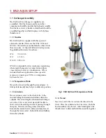
1.2.4  Water Supply 

Th

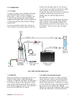
e water supply should be connected to the two 

large hose connectors in the head assembly.  If the 
supply will be at high pressure, then clamps may be 
necessary around the water tubing, to hold the tubes 
on. 

For a slow-response application, where water 
conservation is important, one nozzle can be sealed 
with a cap over the hose connector and water 
supplied only to the other one.

1.2.5  Temperature Probe 

Th

e temperature probe should be inserted down the 

stem adapter as far as it will go. A little Vaseline 
smeared on the sha

ft

 will help it go in more easily, 

and will also ensure an air-tight 

fi

tting. 

Th

e probe 

should be plugged into the temperature data logger, 
which should be put in its own plastic bag to protect 
it, once it has been launched.

1.3  Water Flow 

1.3.1  Water Source 

Th

e water entering the instrument should come 

direct from the sampling point, below the surface, 
and should not have been exposed to any air-water 
interface en route.  

Th

e water should be clean and 

free from debris.  If necessary, it should be 

fi

ltered 

(but not with charcoal) before entering the exchanger.  

Th

e preferred delivery system is a submerged pump, 

delivering the water at fairly low pressure, straight 
from the sampling point to the exchanger.  

Th

ree 

sizes of spray nozzle are supplied.  

Th

e choice will 

depend on the pump performance and the speed of 
response required. 

1.3.2.  Water Level 

With the water 

fl

owing, a spray will be observed 

inside the body of the exchanger.  Water will 

accumulate inside the base and over

fl

ow out through 

the hose connector(s).  If the 

fl

ow rate is very high it 

may be necessary to utilize both hose connectors.  

Th

e level may also start to rise too high inside the 

body of the exchanger.  To correct, either reduce the 

fl

ow rate or purchase the optional 12” cylinder.  A 

high water level inside the exchanger is no problem 
provided it is no more than 1/3 of the way up the 
exchanger and is stable. 

If the water level rises slowly but continuously up the 
cylinder it will be due to the water source being 
completely without dissolved air.  To correct this a 
bleed may be added to the return air path from the 
RAD7.  It should be a long piece of tubing open at 
one end and connected with a T-connector to the 
tubing between the head assembly and the check 
valve.

1.4  Air Flow 

1.4.1  Continuous Pumping 

If you choose “

SETUP, PUMP, ON [ENTER]

” and 

SETUP, MODE, SNIFF [ENTER]

”, then the pump 

will run continuously, regardless of the length of the 
cycles, or status of the RAD7, and the RAD7 will 
count only 218-Po decays.  In this operational mode, 
the system will have the fastest response time, but 
desiccant is quickly hydrated. 

1.4.2  Pump on “Auto” 

Th

e pump, in auto operation, pumps for 

fi

ve minutes 

at the beginning of every cycle and then for one 
minute in every 

fi

ve. 

Th

e length of each cycle is 

chosen by the user.  Short cycle times will involve 
more pumping and speed up the response of the 
instrument, but will consume more desiccant. Longer 
cycle times will give better statistical precision to the 
individual readings, and will conserve desiccant and 
memory space. 

For rapidly changing concentrations of radon in the 
water, 10 minute cycles, with the PUMP on AUTO 
and MODE on SNIFF, may be a suitable compromise, 
though not giving fastest response. 

1.4.3  Mode set to “Auto” 

For very low concentrations, or when long-term 
monitoring is desired, long cycle times of an hour or 
longer, with the PUMP and MODE set to AUTO, 
may make good sense. 

Section 1 


RAD AQUA Setup

 8

Содержание RAD AQUA

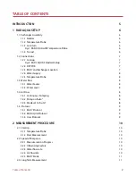
Страница 1: ...RAD AQUA Continuous Radon in Water Accessory for the RAD7 User Manual...

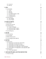
Страница 2: ...rature Probe 8 1 3 Water Flow 8 1 3 1 Water Source 8 1 3 2 Water Level 8 1 4 Air Flow 8 1 4 1 Continuous Pumping 8 1 4 2 Pump on Auto 8 1 4 3 Mode set to Auto 8 1 5 Protocol 9 1 5 1 RAD7 Protocol 9 1...

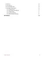
Страница 3: ...Exchanger to RAD7 method 2 14 4 4 Speed of Response 15 5 DRYSTIK 16 5 1 Passive DRYSTIK 16 5 2 Active DRYSTIK 16 5 3 E ect on Response Time 16 5 4 Custom designed Active DRYSTIK 16 6 BOATING 18 6 1 Re...

Страница 4: ...ant Regeneration 20 7 5 RAD AQUA Troubleshooting 20 7 5 1 Rising Water Level 20 7 5 2 Spray Chamber Fills With Water 21 7 5 3 Air Path Integrity 21 7 5 4 Poor Spray Formation 21 7 5 5 Water Overflowin...

Страница 5: ...temperature the coe cient is about 0 25 That means there is four times higher concentration of radon in the air than in the water so there is in e ect a gain of four times in the sensitivity of the s...

Страница 6: ...plications where speed of response is a major goal WL1 is a compromise between the two 1 1 2 Temperature Probe The probe is inserted through the stem adapter A little petroleum jelly may help it to sl...

Страница 7: ...nt left at this end to the air inlet filter with 1 8 ID tubing at the filter end which is then placed on the RAD7 INLET The Luer taper ensures an airtight connection Fig 2 RAD7 AQUA Standard Setup 1 2...

Страница 8: ...ill be observed inside the body of the exchanger Water will accumulate inside the base and overflow out through the hose connector s If the flow rate is very high it may be necessary to utilize both h...

Страница 9: ...ntrations to gain better statistics choose AUTO SETUP THORON Choose OFF SETUP PUMP Choose ON or AUTO depending on choice see above SETUP TONE Choose what you like SETUP FORMAT Choose what you like but...

Страница 10: ...100 counts would give a reading with a standard deviation of 10 At very low concentrations it may take hours and averaging over many cycles to reach a su ciently precise value 2 2 2 In uencing Factor...

Страница 11: ...QUA can be running with a low water flow rate and the RAD7 pump can be on AUTO also For fast response however it is essential to force the RAD7 to stay in SNIFF mode Setup Mode Sniff ENTER It will the...

Страница 12: ...radon concentrations This water temperature data is obtained by exporting it from the temperature logger software see Section 3 1 5 below For specific instructions on downloading and graphing RAD7 dat...

Страница 13: ...emperature data is stored in the temperature logger It is necessary to download the RAD7 data to a PC preferably using DURRIDGE s CAPTURE software and to download the temperature logger data using the...

Страница 14: ...say 4 L min will mean a time delay for the thoron to reach the exchanger of no more than 2 5 seconds 4 3 2 Exchanger to RAD7 method 1 The RAD7 pump will typically generate an air flow rate of around 0...

Страница 15: ...ponse of the RAD7 to thoron is limited not be the half life of the polonium daughter but by the time it takes to get the sample into the measurement chamber We have seen that with the highest sensitiv...

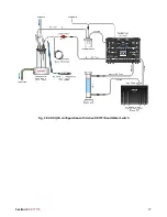
Страница 16: ...7 will keep the air sample in the RAD7 below 7 RH It will also last for a very long time and add only a tiny volume to the air loop maintaining a fast response See Fig 3 5 3 E ect on Response Time Wit...

Страница 17: ...Fig 3 RAD AQUA con guration with Active DRYSTIK and Water Switch Section 5 DRYSTIK 17...

Страница 18: ...eded increases significantly The Rule 3700 delivers 6 L min through a W4 nozzle but it takes over 15A One 8 hour run would completely discharge a 120 AH battery 6 1 2 Minimizing T1 with reduced air vo...

Страница 19: ...reducing the advantage of the three pumps to only 5 to 10 minutes But with the Rule 3700 the extra 20L to 40L of water would take only 3 or 4 minutes to deliver thus preserving almost all the 20 minu...

Страница 20: ...ir sockets and push the lid onto its hinges The wrap will make the RAD7 almost watertight If it tears it can be easily replaced at any time The instrument should in any case be returned every year for...

Страница 21: ...or leaks 7 5 3 Air Path Integrity When drawing a sample from a remote location air path integrity is essential to prevent dilution of the sample with ambient air Always make sure that there are no lo...

Страница 22: ...ter inputs into river dominated areas important The Chao Phraya River Gulf of Thailand Limnology and Oceanography 51 2232 2247 Povinec P P P K Aggarwal A Aureli W C Burnett E A Kontar K M Kulkarni W S...

Страница 23: ...2008 Determination of transport rates in the Yellow River Bohai Sea mixing zone via natural geochemical tracers Continental Shelf Research 28 19 2700 2707 167 Povinec P P H Bokuniewicz W C Burnett J C...

Страница 24: ...67 9556 Fax 978 667 9557 Web www durridge com Email service durridge com Copyright 2018 DURRIDGE Company Inc All rights reserved DURRIDGE the DURRIDGE logo and the Works with the DURRIDGE logo are tra...

Отзывы: