EN
1805V002
7560100010L02
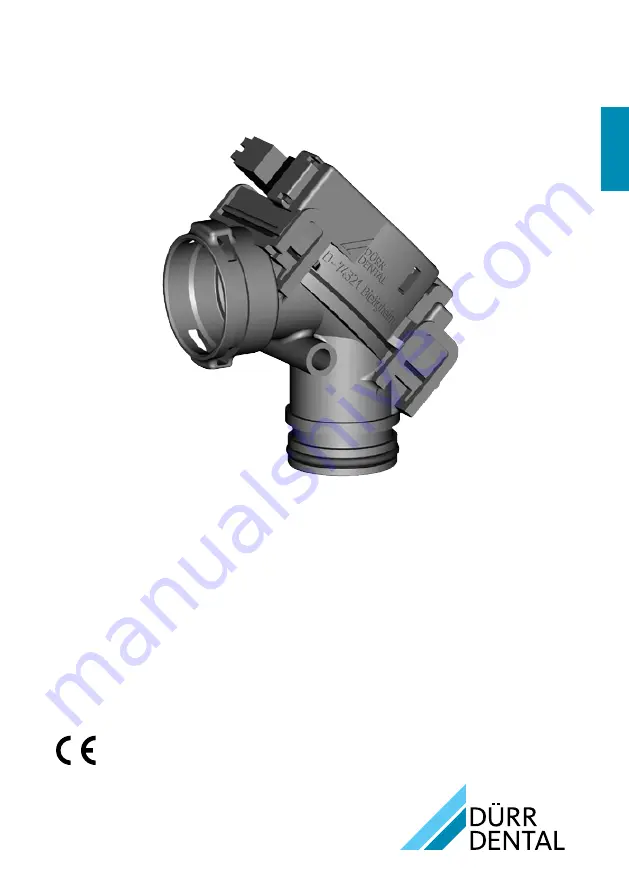
Installation instructions
Station selection valve
Страница 1: ...EN 1805V002 7560100010L02 Installation instructions Station selection valve ...
Страница 2: ......
Страница 3: ...vice technicians 13 EN Contents Important information 1 About this document 2 1 1 Warnings and symbols 2 1 2 Copyright information 2 2 Safety 3 2 1 Intended purpose 3 2 2 Intended use 3 2 3 Improper usage 3 2 4 Systems connection with other devices 3 2 5 General safety notes 3 2 6 Specialist personnel 3 2 7 Protection from electric shock 3 2 8 Only use original parts 4 2 9 Transport 4 2 10 Disposa...
Страница 4: ...f the unit Failure to comply with the specifications of these installation instructions will void the warranty Dürr Dental will not assume any liability for the safe operation and the safe functioning of the unit 1 1 Warnings and symbols Warnings The warnings in this document are intended to draw your attention to possible injury to persons or damage to machinery The following warning symbols are ...
Страница 5: ...m distance of 30 cm between the unit and mobile radio devices i i Note that cable lengths and cable extensions have effects on electromagnetic compatibility 2 Safety Dürr Dental has designed and constructed this unit so that when used properly and for the in tended purpose it does not pose any danger to people or property Nevertheless residual risks can remain You should therefore observe the foll...
Страница 6: ...unction of the unit NOTICE Erroneous operation mode due to use immediately adjacent to other devices or with other stacked de vices i i Do not stack the unit together with other devices i i If this is unavoidable note any poten tial impacts on the operation mode 2 8 Only use original parts i i Only use Dürr Dental parts or accessories and special accessories specifically approved by Dürr Dental i ...
Страница 7: ...lve 7560 500 XX or Place selection valve 75605000XX Connection parts Quick start instructions 3 2 Accessories The following items are required for operation of the device depending on the application DürrConnect20 system set 0700 700 50 Relay box 7560 565 50 3 3 Spare parts Information about replacement parts is available from the portal for authorised specialist dealers at www duerrdental net Pro...
Страница 8: ...elative humidity 95 Air pressure hPa 500 1060 Ambient conditions during operation Temperature C 10 to 40 Relative humidity 75 Air pressure hPa 700 1060 Classification Medical Devices Directive 93 42 EEC Class I Electromagnetic compatibility EMC Interference emission measurements High frequency emissions in accordance with CISPR 11 Class B Harmonics in acc with IEC 61000 3 2 Not applicable Voltage ...
Страница 9: ...late is located on the top of the valve 1 1 Type plate 4 2 Evaluation of conformity This device has been subjected to conformity acceptance testing in accordance with the cur rent relevant European Union guidelines This equipment conforms to all relevant require ments EN ...
Страница 10: ... power 1 Solenoid valve 2 Valve membrane Place selection valve open If the suction hose is taken out of the hose manifold a voltage is applied to the solenoid valve on the place selection valve and the solenoid valve is actuated With the vacuum of the suction unit the vol ume between the valve cap and membrane is drawn by suction until it is empty and the membrane is consequently raised The raised...
Страница 11: ...r 12 o clock suction 6 2 Hose materials For waste connections and suction lines only use the following hose types Flexible spiral hoses made of PVC with inte grated spiral or equivalent hoses Hoses that are resistant to dental disinfectants and chemicals Plastic hoses will display signs of ageing over time Therefore they should be in spected regularly and replaced as neces sary The following types...
Страница 12: ...king on the unit i i Wear protective equipment when working e g liquid tight protective gloves protective goggles face mask i i Locate a suitable installation point in the treat ment unit Observe the installation position i i Fasten the place selection valve i i Connect the hoses to the connecting sleeves i i Secure the hoses with hose clamps 7 4 Electrical connections i i Connect the control line...
Страница 13: ...4 V AC DC 1 Hose manifold 2 Station selection valve 3 Rinsing unit 4 Spittoon valve X1 Cleaning button for switch control panel X3 Solenoid valve X4 Control line for suction unit X5 Power supply K1 Suction unit relay N2 Float sensor detection N3 Cleaning button detection sensor 5 Suction machine relay in the treatment unit EN ...
Страница 14: ... on the unit power switch or the main sur gery switch i i Carry out an electrical safety check in accord ance with applicable local regulations e g the German Ordinance on the Installation Opera tion and Use of Medical Devices Medizin produkte Betreiberverordnung and record the results as appropriate e g in the technical log book i i Check the aspiration function i i Check the connections hoses an...
Страница 15: ...RNING Infection due to contaminated unit i i Clean and disinfect the suction before working on the unit i i Wear protective equipment when working e g impermeable gloves protective goggles and mouth and nose protection Fault Probable cause Solution No suction power Valve membrane closed i i Check voltage on solenoid valve i i Clean valve membrane i i Clean air ducts i i Check vacuum Troubleshootin...
Страница 16: ......
Страница 17: ......
Страница 18: ......
Страница 19: ......
Страница 20: ...Hersteller Manufacturer DÜRR DENTAL SE Höpfigheimer Str 17 74321 Bietigheim Bissingen Germany Fon 49 7142 705 0 www duerrdental com info duerrdental com ...