Dürkopp Adler D669 Скачать руководство пользователя страница 46

Programming

44

Operating Instructions D669 M-TYPE DELTA - 00.0 - 10/2020

5.2

Navigating the Commander DELTA control 
panel

You navigate the control panel by tapping the screen with your 
fingers. There is no need for an input device.

You can open menus by pressing the corresponding button with 
your finger. You switch between the different pages of the start 
screen by swiping with one finger.

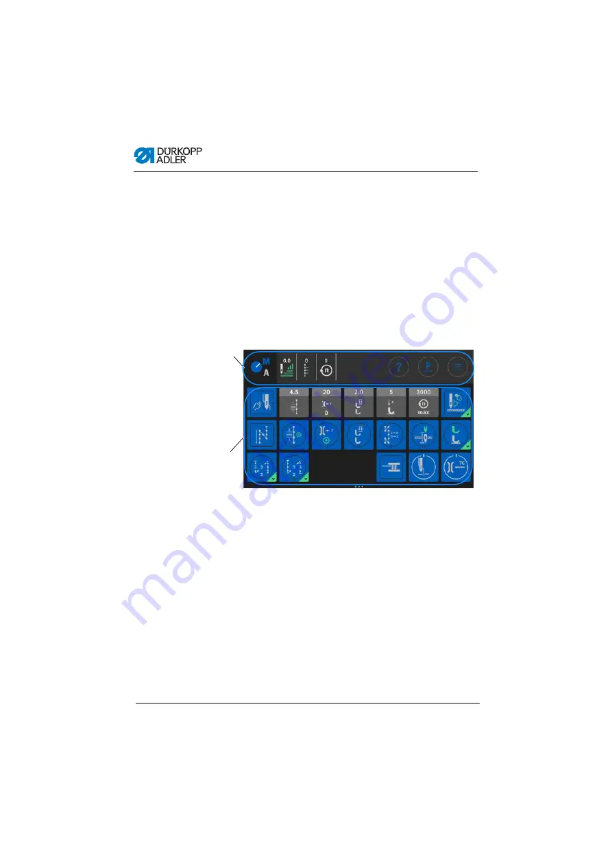
You can modify the information displayed in the status bar (1). 
You can also adjust the tiles shown on the three pages of the main 
screen (2). You customize the information using the control panel 
settings, 

p. 69

.

Fig. 22: Navigating the Commander DELTA control panel

(1) - Status bar

(2) - Main screen

Содержание D669

Страница 1: ...D669 M TYPE DELTA Operating Instructions...

Страница 2: ...er AG and protected by copyright Any reuse of these contents including extracts is prohibited without the prior written approval of D rkopp Adler AG Copyright D rkopp Adler AG 2020 IMPORTANT READ CARE...

Страница 3: ...ng the needle thread 24 4 6 Winding the hook thread 28 4 7 Changing the bobbin 31 4 8 Thread tension 32 4 8 1 Adjusting the needle thread tension 33 4 8 2 Adjusting the hook thread tension 33 4 9 Adju...

Страница 4: ...Using bobbin wind mode 95 5 7 Using Automatic mode 95 5 7 1 Sewing in Automatic mode 98 5 7 2 Canceling a program in Automatic mode 99 5 8 Using Programming mode 100 5 8 1 Managing programs 101 5 8 2...

Страница 5: ...ng light 153 7 14 Assembling the CCEA sewing light 157 7 15 Assembling the sewing light with table clamp 160 7 16 Electrical connection 163 7 16 1 Connecting the sewing light transformer 163 7 16 2 Es...

Страница 6: ...Table of Contents 4 Operating Instructions D669 M TYPE DELTA 00 0 10 2020...

Страница 7: ...partoftheproductandkeepiteasily accessible 1 1 For whom are these instructions intended These instructions are intended for Operators This group is familiar with the machine and has access to the inst...

Страница 8: ...ustment Cover Specifies which covers must be disassembled in order to access the components to be set Steps to be performed when operating the machine sewing and equipping Steps to be performed for se...

Страница 9: ...hazard symbols levels of danger and their signal words are described separately in the chapter Safety p 9 Location information If no other clear location information is used in a figure indications o...

Страница 10: ...use Unauthorized modifications to the machine Use of untrained personnel Use of unapproved parts Transport D rkopp Adler cannot be held liable for breakage and transport damages Inspect the delivery i...

Страница 11: ...chine at the main switch or disconnect the power plug Replacing the needle or other sewing tools Leaving the workstation Performing maintenance work and repairs Threading Missing or faulty parts could...

Страница 12: ...age Stop working if you notice any changes to the machine Report any changes to your supervisor Do not use a damaged machine any further Safety equipment Safety equipment should not be disassembled or...

Страница 13: ...danger to personnel CAUTION with hazard symbol If ignored moderate or minor injury can result CAUTION with hazard symbol If ignored environmental damage can result NOTICE without hazard symbol If igno...

Страница 14: ...that could result in serious or even fatal injury if ignored This is what a warning looks like for a hazard that could result in moderate or minor injury if the warning is ignored DANGER Type and sou...

Страница 15: ...t in property damage if ignored This is what a warning looks like for a hazard that could result in environmental damage if ignored NOTICE Type and source of danger Consequences of non compliance Meas...

Страница 16: ...Safety 14 Operating Instructions D669 M TYPE DELTA 00 0 10 2020...

Страница 17: ...hine description 3 1 Components of the machine Fig 1 Components of the machine 1 Motor driven thread tension 2 Favorite buttons 3 Jog dial 4 Push buttons 5 Service Stop button 6 Electronic stitch regu...

Страница 18: ...ne is intended for industrial use The machine may only be set up and operated in dry conditions on well maintained premises If the machine is operated on premises that are not dry and well maintained...

Страница 19: ...D669 M TYPE DELTA 00 0 10 2020 17 3 3 Declaration of Conformity ThemachinecomplieswithEuropeanregulationsensuringhealth safety and environmental protection as specified in the declara tion of conform...

Страница 20: ...Machine description 18 Operating Instructions D669 M TYPE DELTA 00 0 10 2020...

Страница 21: ...1 Preparing the machine for operation Complete the following steps in preparation of sewing before starting to work Inserting or changing the needle Threading the needle thread Threading or winding th...

Страница 22: ...front of the control The control and the control panel of the machine start up 3 Press the pedal backwards when prompted to do so on the display The machine performs a reference run and is afterwards...

Страница 23: ...htness of the sewing lights via software at the control panel Burger menu Settings User Configuration Machine Switching on and off the sewing lights By default there is no simple way to switch the sew...

Страница 24: ...e screw 2 3 Pull the needle out towards the bottom CAUTION Risk of injury from sharp parts Puncture possible Switch off the machine before you insert or change the needle NOTICE Property damage may oc...

Страница 25: ...atthegroove 3 facesthehook 4 5 Tighten the screw 2 Order Always adjust the clearance between the hook and the needle after changing to a different needle strength Service Instructions Disturbance An i...

Страница 26: ...med Threading one needle The instructional video starts automatically 3 Click on the tile in the left menu bar The instructional video Threading two needles starts automatically To thread the needle t...

Страница 27: ...read counterclockwise from the tube 1 around the pretension 7 5 Feed the thread clockwise through the rear tensioner 6 6 Feedthethreadclockwisearoundthepin 4 andkeepfeeding it clockwise through the fr...

Страница 28: ...left to right and then from top to bottom through the rear hole of the needle thread regulator 11 9 Insert the thread from the right to the left through the lower guide of the thread lever 12 10 Inse...

Страница 29: ...almost without touching it and in such a way that it only makes contact with the guides above and below the thread clamp 15 Insert the thread through the thread guide 8 on the needle bar block 16 Inse...

Страница 30: ...thread winding itself around the bobbin shaft which may cause damage to the winder To wind the hook thread 1 Fit the thread reel on the reel stand The unwinding bracket must stand directly above the...

Страница 31: ...ht through the first hole and from right to left through the second hole 4 Feed the thread through the third hole of the thread guide 2 from left to right before feeding it clockwise around the pre te...

Страница 32: ...11 Pull the winder lever 4 up The winding process starts and ends automatically when the bobbin is full The winder lever 4 returns to its lower position Information The hook thread is normally wound...

Страница 33: ...er WARNING Riskofinjuryfromneedletipandmovingparts Puncture cutting and crushing possible Turn off the machine before changing the bobbin NOTICE Property damage may occur The surface of the bobbin may...

Страница 34: ...ction 2 The bobbin must rotate in the direction of the arrow when pulling out the thread 8 Insert the bobbin case upper section 2 again 9 Close the hook cover 6 4 8 Thread tension Together with the ho...

Страница 35: ...tion refer to the chapter Programming p 43 4 8 2 Adjusting the hook thread tension 1 Identical needle thread and hook thread tension 2 Hook thread tension higher than needle thread tension 3 Needle th...

Страница 36: ...at the resulting seam pattern is uniform The basic setting for the tension spring is performed as follows When the bobbin case contains a full bobbin it must sink slowly under its own weight The braki...

Страница 37: ...ckwise 4 9 Adjusting the needle thread regulator The needle thread regulator determines the tension applied to guide the needle thread around the hook Proper setting Theloopoftheneedlethreadslidesatlo...

Страница 38: ...tension Slide the needle thread regulator 1 to the left 2 Tighten the screw 2 4 10 Lifting the sewing feet Fig 16 Lifting the sewing feet To lift the sewing feet 1 Press the pedal 1 halfway back The...

Страница 39: ...stitch regulator on the machine arm reduces the stitch length down to sewing backwards in the lower end position Fig 17 Sewing backwards with the stitch regulator 1 Slowly push the stitch regulator 1...

Страница 40: ...s on the push button panel The machine has push buttons on the machine arm which can be used to activate specific functions while sewing You can define the settings in the software p 43 4 13 1 Activat...

Страница 41: ...es configured so that selecting the button will bring the needle up to the top dead center Bartack suppression This button cancels the general setting for sewing start and end bartacks If bartacks are...

Страница 42: ...tton functions from the push button panel to the favorite buttons Select a function that you frequently use so that you can switch it on faster while sewing Fig 19 Assigning a function to the favorite...

Страница 43: ...pedal when you fingers are in the area of the needle tip 1 Position 1 2 Position 0 3 Position 1 4 Position 2 Condition Processes Before starting sewing Initial situation Pedal in rest position positio...

Страница 44: ...creasing speed the further forward the pedal is pressed Sew over thicker parts of the material Switch on the elevated sewing foot stroke with the knee button p 38 Change the stitch length Activate the...

Страница 45: ...nder DELTA Fig 21 Control panel Commander DELTA All settings in the software are performed using the Commander DELTA control panel Information If a value is entered that is not within the specified va...

Страница 46: ...open menus by pressing the corresponding button with your finger You switch between the different pages of the start screen by swiping with one finger You can modify the information displayed in the s...

Страница 47: ...mode Burger menu A window opens that lets you select Automatic mode Manual mode Programming mode or Settings Context sensitive help Start by pressing the gray question mark before pressing the area fo...

Страница 48: ...value of the value range Blue tiles multifunction You can active or deactivate dark tiles encircled by a white line and showing a blue triangle in the corner by pressing A long press opens a menu that...

Страница 49: ...ings without having to wait for the control panel to finish starting up You can select these options as soon as their icons are displayed on the control panel After entering your user login you will b...

Страница 50: ...logged in user to customize the software interface to their specific needs To access the User Configuration 1 Press the symbol to bring up the navigation pane This opens the navigation interface Fig 2...

Страница 51: ...tion 5 3 1 Setting the language Here you can set the language of the software Fig 26 Setting the language 1 To set the language 1 Press on the language indicator 1 A list holding the language selectio...

Страница 52: ...htness Here you can adjust the brightness of the control panel Fig 28 Adjusting the brightness 1 To set the brightness 1 Press on the brightness indicator 1 2 Enter the desired value using the keyboar...

Страница 53: ...the audio volume indicator 1 2 Enter the desired value using the keyboard or the buttons or The volume of the control panel is adjusted 5 3 4 User Management administration This section is locked if...

Страница 54: ...Setting the smart keys configuration 1 To set the smart keys configuration 1 Press on the sub item Smart keys configuration 1 This opens the interface of the fast menu key configuration Fig 31 Settin...

Страница 55: ...ign to the button 4 Press to select the option Not stored or Stored 5 Press outside the selection to exit the selection The adjusted settings are stored 5 3 6 Setting the screen configuration The scre...

Страница 56: ...change this setting at the Technician level as needed The following is an explanation of the user Default Technician who is set up as the default user You can set up any number of users and roles that...

Страница 57: ...s Logout 1 This opens the Login interface 3 Enter technician and 25483 for username and password 4 Press The user is logged in To access User Management 1 Press the symbol to bring up the navigation p...

Страница 58: ...ess the item User Configuration 3 on the left 4 Press the item User Management 4 on the right The user management interface opens which may look different depending on the user Fig 36 User Management...

Страница 59: ...d users p 62 Detailed explanations are provided further below To the right of the tabs you will find the list 2 of created roles users varying with the tab 1 you selected On the far right you will fin...

Страница 60: ...e following interface Fig 38 Managing roles Press the tab 1 reserved for the Roles on the left hand side Deleting a role To delete a role 1 Press the desired role The role is highlighted in blue 2 Pre...

Страница 61: ...t Technician you can only select role derivations up to the role of Technician You can adjust this setting in the authorizations of the roles table below Settings of the roles Read Edit Access Menu it...

Страница 62: ...Guide reference position Edit Stitch length Edit Switch Stitch Length Edit Needle thread tension Edit Switch Thread Tension Edit Sewing foot pressure Edit Sewing foot stroke Edit Switch Foot Stroke A...

Страница 63: ...ng Access Start bartack submenu Access End bartack submenu Access Foot lifting submenu Access Thread clamp submenu Access Pointing position submenu Access 2nd Edge guide position submenu Access Reset...

Страница 64: ...erface Fig 39 Managing users 1 Press the tab 1 reserved for the Users on the left hand side This interface appears Fig 40 Managing users 2 The left hand side holds a list of all users 2 that have been...

Страница 65: ...ist it has been deleted Information Users with a symbol behind their names have been created at the factory They cannot be deleted Creating a new user To create a new user 1 Press The list shows a new...

Страница 66: ...ing in Login with NFC token Login by NFC chip allowed or not allowed Login with USB key Login by USB key allowed or not allowed Automatic login during system start Automatic login when machine starts...

Страница 67: ...ill be logged in automatically when the machine is switched on This does not require any type of authorization The following explains how you can switch users To access User Management 1 Press the sym...

Страница 68: ...p 62 The user can log in immediately with this login information Logging in with username and password To log in with username and password 1 Enter username and password 2 Press If the login informati...

Страница 69: ...ng in with NFC chip Assigning an NFC chip to a user To assign an NFC chip to a user 1 Select a user in User Management or create a new user p 62 2 Press the item Login with NFC chip A new window opens...

Страница 70: ...functions are always implemented immediately All the major sewing parameters can be changed manually during the sewing process Automatic mode Automatic mode allows for the execution of setups seam pr...

Страница 71: ...on interface Fig 42 Using Manual mode 2 Press Manual mode 1 The interface of Manual mode opens 5 6 1 Setting up the user interface You can customize the arrangement of the tiles and the appear ance of...

Страница 72: ...face 1 2 Press Settings 1 This opens the Settings interface Fig 44 Setting up the user interface 2 3 Go to Screen configuration 2 and press on Manual mode Main screen configuration 3 The interface use...

Страница 73: ...o return to Settingsor to return toManualmode Adjusting the information displayed in the status bar To adjust the appearance of the status bar 1 Go to Settings see above Fig 46 Setting up the user int...

Страница 74: ...5 3 Press and hold the desired symbol and drag it to move it into or out of the status bar 4 Press to return to Settingsor to return toManualmode Default status bar settings Fig 48 Default status bar...

Страница 75: ...and how they affect the parameters are described further below To access the parameter settings 1 Press the symbol to bring up the parameter pane This opens the parameter settings interface Fig 49 Set...

Страница 76: ...ntrol panel Value range 00 0 12 0 depending on sewing equipment and subclass Additional value sewing foot stroke The 2nd value for the sewing foot stroke can be switched on using a button on the push...

Страница 77: ...Correction speed effect Correction speed effect Value range On Off see p 79 Stitch length The stitch length changes slightly depending on the speed For this reason the stitch length can be adjusted a...

Страница 78: ...by the software Needle thread tension Depending on the material thickness the needle thread tension can be adjusted to different material thicknesses by the software Sewing foot pressure The sewing f...

Страница 79: ...nt of the remaining thread monitor is present on the machine Monitor mode allows for optical monitoring of the bobbin Sewing stop Sewing stops and a notice is shown on the display when the bobbin is d...

Страница 80: ...variable value which depends on the size of the bobbin and the thickness of the thread Value range 00000 99999 Sewing stop Sewing stops and a notice is shown on the display when the bobbin is detecte...

Страница 81: ...ed to the following specific parameters Setting mode Description linear In the linear setting the size of the parameter increases or decreases steadily as the speed increases The increase decrease of...

Страница 82: ...ng on subclass Speed at which the increase reduction of stitch length should start Max Sewing speed Value range 0000 4000 rpm depending on subclass Speed up to which the increase reduction of stitch l...

Страница 83: ...ing on subclass Speed at which the increase in needle thread tension should start Max Sewing speed Value range 0000 4000 rpm depending on subclass Speed up to which the increase in needle thread tensi...

Страница 84: ...t pressure Value range 00 20 Maximum sewing foot pressure reached at the upper speed limit Min Sewing speed Value range 0000 4000 rpm depending on subclass Speed at which the increase in sewing foot p...

Страница 85: ...setting the size of the parameter increases or decreases steadily as the material thickness increases The increase decrease of the parameter depends on the limits set for the minimum and the maximum...

Страница 86: ...lue range 00 0 10 0 mm Material thickness at which the increase in sewing foot stroke should start Max Material thickness Value range 00 0 10 0 mm Material thickness up to which the increase in sewing...

Страница 87: ...range 00 0 10 0 mm Material thickness at which the increase reduction of stitch length should start Max Material thickness Value range 00 0 10 0 mm Material thickness up to which the increase reduc ti...

Страница 88: ...rease in needle thread tension should occur 2 OnOff Min Material thickness Value range 00 0 10 0 mm Material thickness from which the 2nd needle thread tension should be used 2 On Min Material thickne...

Страница 89: ...assigned to a physical output at the Technician level This requires that the parameter Additional I O Configuration can be configured at the Technician level for more details refer to the explanation...

Страница 90: ...e needle thread lies on the underside of the sewing material Value range On Off Seam begin bartack settings Bartack at seam begin Value range On Off Number of stitches backwards Value range 01 50 Numb...

Страница 91: ...is function can only be used meaningfully if the speed is set very low for the bartack Value range On Off Needle thread tension default If this function is active the same needle thread tension is use...

Страница 92: ...st section of the bartack can be programmed with a different number of stitches All previous sections have the preset number of stitches from the settings for the end bartack On Off Number of stitches...

Страница 93: ...are described in more detail after the table Icon Parameter Setting Seam Parameter Stitch length Value range 00 0 12 0 mm depending on the sewing equipment and the subclass Needle thread tension Valu...

Страница 94: ...at Sewing stop Value range 00 20 mm depending on subclass Light barrier optional additional equipment The light barrier detects the beginning and the end of the material After a sig nal was detected...

Страница 95: ...sistent seam quality ornamental stitch bartack Value range 0000 1000 ms Stitch length default If this function is active the same needle stitch length is used for the bartack as the one set in Manual...

Страница 96: ...alue range 01 50 Number of bartack sections Value range 01 10 First bartack section The 1st section of the bartack can be programmed with a different number of stitches All subsequent sections have th...

Страница 97: ...f rotations To use bobbin wind mode 1 When setting up the user interface p 69 drag the tile for bobbin wind mode onto the main screen 2 Press to return to Manual mode 3 Press on the bobbin wind mode s...

Страница 98: ...Fig 50 Using Automatic mode 1 2 Press Automatic mode 1 The interface of Automatic mode opens The program stored last is loaded The display shows tiles and information below the upper bar that vary wit...

Страница 99: ...a seam program Seam segment including information on the settings for seam beginning seam and seam end Display of the entire program including its seams and segments Adjustment factors that can still...

Страница 100: ...omatic mode Possible actions in the course of the seam The following table lists the functions that can be performed in the course of the seam 1 Progress in the segment 2 Progress in the program Butto...

Страница 101: ...inues from the same point when sewing resumes 2 To cancel the program completely press the pedal all the way backwards again The program is canceled and the machine starts from the first seam section...

Страница 102: ...djust existing programs To access Programming mode 1 Press the symbol to bring up the navigation pane This opens the navigation interface Fig 53 Using Programming mode 1 2 Press Programming The user i...

Страница 103: ...tiles to the main screen or the status bar Managing the items is quick and easy thanks to the buttons listed below Create a new program Delete a selected program Copy and insert a program Search for a...

Страница 104: ...of a seam 1 Press on the desired seam The seam is highlighted in blue Fig 55 Editing the segments of a seam 1 2 Press on the symbol The interface used for setting the parameters opens Fig 56 Editing...

Страница 105: ...e segment Copy and insert a segment Icon Parameter Setting Additional values Additional value stitch length The 2nd value for the stitch length can be switched on using a button on the push button pan...

Страница 106: ...ou select the start segment and the end segment from a program and define how often you wish the selected segments to be sewn On Off Start Segment Value range 00 30 0 the cycle starts with the first s...

Страница 107: ...9 Correction speed effect Correction speed effect Value range On Off see p 109 Stitch length The stitch length changes slightly depending on the speed For this rea son the stitch length can be adjuste...

Страница 108: ...al thicknesses by the software Needle thread tension Depending on the material thickness the needle thread tension can be adjusted to different material thicknesses by the software Sewing foot pressur...

Страница 109: ...he remaining thread monitor is present on the machine Monitor mode allows for optical monitoring of the bobbin Sewing stop Sewing stops and a notice is shown on the display when the bobbin is detected...

Страница 110: ...s a very variable value which depends on the size of the bobbin and the thickness of the thread Value range 00000 99999 Sewing stop Sewing stops and a notice is shown on the display when the bobbin is...

Страница 111: ...the following specific parameters Setting mode Description linear In the linear setting the size of the parameter increases or decreases steadily as the speed increases The increase decrease of the pa...

Страница 112: ...nding on subclass Speed at which the increase reduction of stitch length should start Max Sewing speed Value range 0000 4000 rpm depending on subclass Speed up to which the increase reduction of stitc...

Страница 113: ...ding on subclass Speed at which the increase in needle thread tension should start Max Sewing speed Value range 0000 4000 rpm depending on subclass Speed up to which the increase in needle thread tens...

Страница 114: ...t pressure Value range 00 20 Maximum sewing foot pressure reached at the upper speed limit Min Sewing speed Value range 0000 4000 rpm depending on subclass Speed at which the increase in sewing foot p...

Страница 115: ...ng the size of the parameter increases or decreases steadily as the material thickness increases The increase decrease of the parameter depends on the limits set for the minimum and the maximum materi...

Страница 116: ...nge 00 0 10 0 mm Material thickness at which the increase in sewing foot stroke should start Max Material thickness Value range 00 0 10 0 mm Material thickness up to which the increase in sewing foot...

Страница 117: ...00 0 10 0 mm Material thickness at which the increase reduction of stitch length should start Max Material thickness Value range 00 0 10 0 mm Material thickness up to which the increase reduc tion of...

Страница 118: ...in nee dle thread tension should occur 2 Value On Off Min Material thickness Value range 00 0 10 0 mm Material thickness from which the 2nd needle thread tension should be used 2 Value On Min Material...

Страница 119: ...ximum speed reached at the upper material thickness limit Min Material thickness Value range 00 0 10 0 mm Material thickness at which the increase in sewing speed should start Max Material thickness V...

Страница 120: ...n be entered On Off Stitch length of stitches forward Value range 01 0 12 0 mm depending on subclass Stitch length of backwards stitches Value range 01 0 12 0 mm depending on subclass Speed in bartack...

Страница 121: ...ack can be programmed with a different number of stitches All subsequent sections have the preset number of stitches from the settings for the start bartack On Off Number of stitches Value range 01 50...

Страница 122: ...tension Value range 01 99 Sewing foot pressure Value range 01 20 Sewing foot stroke Value range 1 0 9 0 mm Seam length in segment or Number of stitches in segment You can set the active option at the...

Страница 123: ...sewing material The feed of the two rollers is calculated automatically based on the stitch length of the machine An adjustment may be nec essary depending on the application The rollers of the pulle...

Страница 124: ...r optional additional equipment The light barrier detects the beginning and the end of the material After a sig nal was detected sewing can continue automatically with the specifically set parameters...

Страница 125: ...the light barrier must detect a signal to allow the machine to sew If the function is inactive sewing can take place without signal detection Value range On Off Signal detection at seam end The signal...

Страница 126: ...be configured at the Technician level for more details refer to the explanation in the Service Instructions 5 8 8 SettingtheSegment End Seam Endparameters TherearevariousoptionsforsettingtheSegmentEnd...

Страница 127: ...ed for the bartack as the one set in Manual mode If this function is deactivated a custom input can be entered On Off Stitch length of stitches forward Value range 01 0 12 0 mm depending on subclass S...

Страница 128: ...ack can be programmed with a different number of stitches All subsequent sections have the preset number of stitches from the settings for the start bartack On Off Number of stitches Value range 01 50...

Страница 129: ...g exporting programs Programs cannot be imported or exported by the Default User This process requires that the user be logged in as a technician Service Instructions Icon Menu item Setting option Nee...

Страница 130: ...to a USB key 3 Plug the USB key into the port on the control panel 4 Open the burger menu and select the menu Settings Software Update A window listing the files stored on the USB key opens 5 Select t...

Страница 131: ...ists Service Instructions Maintenance intervals WARNING Risk of injury from sharp parts Punctures and cutting possible Prior to any maintenance work switch off the machine or set the machine to thread...

Страница 132: ...sk of injury from flying particles Flying particles can enter the eyes causing injury Wear safety goggles Hold the compressed air gun so that the particles do not fly close to people Make sure no part...

Страница 133: ...to soiling Knife on the winder for the hook thread 4 Area under the throat plate 3 Hook 2 Area around the needle 1 NOTICE Property damage from solvent based cleaners Solvent based cleaners will damage...

Страница 134: ...rfaces use the cleaner MONOCLEAN X400 Follow the instructions on how to use this cleaning agent to prevent damage to the machine 6 2 Lubricating CAUTION Risk of injury from contact with oil Oil can ca...

Страница 135: ...nt 150 C You can order the lubricating oil from our sales offices using the following part numbers 6 2 1 Lubricating the machine head Proper setting The oil level is between the minimum level marking...

Страница 136: ...level marking 3 Pour oil through the refill opening 1 but no higher than the maximum level marking 2 6 2 2 Lubricating the hook The approved oil quantity for hook lubrication is a factory specificati...

Страница 137: ...released amount of oil does not change until the operating time has run a few minutes Sew for several minutes before you check the setting again 6 3 Servicing the pneumatic system 6 3 1 Adjusting the...

Страница 138: ...sting the operating pressure To adjust the operating pressure 1 Pull the pressure regulator 1 up 2 Turn the pressure regulator until the pressure gage 2 indicates the proper setting Increase pressure...

Страница 139: ...Check the level of the water oil mixture in the collection tray 2 Fig 61 Draining the water oil mixture To drain the water oil mixture 1 Disconnect the machine from the compressed air supply 2 Place t...

Страница 140: ...4 Unscrew the filter element 1 5 Blow out the filter element 1 using the compressed air gun 6 Wash out the filter tray using benzine 7 Tighten the filter element 1 8 Tighten the collection tray 2 9 T...

Страница 141: ...Maintenance Operating Instructions D669 M TYPE DELTA 00 0 10 2020 139 6 4 Parts list Apartslistcanbe orderedfromD rkopp Adler Orvisitourwebsite for further information at www duerkopp adler com...

Страница 142: ...Maintenance 140 Operating Instructions D669 M TYPE DELTA 00 0 10 2020...

Страница 143: ...ine Lashing straps and wooden blocks from the machine head the table and the stand Supporting wedges between machine arm and throat plate WARNING Risk of injury from cutting parts Cutting injuries may...

Страница 144: ...nner bars 1 in such a way that the longer end of the head section 8 is above the longer end of the foot struts 5 5 Tighten the inner bars 1 down so that both head sections 8 are at the same height 6 I...

Страница 145: ...The cross strut has elongated holes to allow for the alignment of the pedal 2 Tighten the pedal 4 on the cross strut 3 3 Screw the bracket 6 under the tabletop so that the pedal rod 1 runs to the peda...

Страница 146: ...s sufficient load bearing capacity and strength If you want to make your own tabletop use the dimensions given in the diagram in the Appendix p 203 as a template 7 5 1 Completing the tabletop Thetable...

Страница 147: ...he reel stand 4 into the hole 5 Assemble the reel stand 4 with nut and washer 6 Tighten the thread reel holder and the thread guide on the reel stand 4 in such a way that they are exactly opposite eac...

Страница 148: ...G Risk of injury from moving parts The tabletop can sink under its own weight when the screws on the stand bars are loosened Crushing possible Ensure that your hands are not jammed when loosening the...

Страница 149: ...venly at both sides to prevent it from jamming 3 Tighten the screws 1 on the stand bars 7 7 Assembling the control Fig 68 Assembling the control To assemble the control 1 Screw the control 2 onto the...

Страница 150: ...tabletop 2 Tighten the machine head using the screws 1 WARNING Risk of injury from moving parts The machine head is very heavy Crushing possible Ensure that your hands are not jammed when inserting t...

Страница 151: ...D669 M TYPE DELTA 00 0 10 2020 149 7 9 Disassembling the ring bolt Fig 70 Disassembling the ring bolt To disassemble the ring bolt 1 Loosen the screw 2 2 Remove ring bolt 1 and washer 3 Re tighten the...

Страница 152: ...ilt sensor has been pre assembled 7 11 Changing the handwheel Thehandwheelthatshipswiththemachineisthelargehandwheel The large handwheel can be replaced with the included small handwheel Important Whe...

Страница 153: ...Position the small handwheel 5 above the pulley in such a way that the pin 4 protruding on the inside of the handwheel fits into the matching hole 2 in the pulley 4 Tighten the small handwheel 5 using...

Страница 154: ...ng the knee button To assemble the knee button 1 Screw the knee button 1 in front of the oil pan firmly in place under the tabletop 2 Guide the connecting cable 2 to the back between the oil pan and t...

Страница 155: ...ght LED sewing light Junction box Sewing light transformer Fig 74 Assembling the LED sewing light 1 To assemble the sewing light 1 Switch off the machine 2 Disassemble the covers 1 NOTICE Property dam...

Страница 156: ...TA 00 0 10 2020 Fig 75 Assembling the LED sewing light 2 3 Screw the holder 4 to the head cover using the screw 3 4 Slide the sewing light 5 into the holder 4 and tighten it at the head cover using th...

Страница 157: ...5 Lay the cable 8 inside the machine arm using the clips 7 6 Lay the cable 8 through the guide 6 under the tabletop Fig 77 Assembling the LED sewing light 4 7 File some material off the cover 1 marked...

Страница 158: ...ngth of the cables 10 Pull the power cable 10 out of the control and insert it into the junction box 11 11 Insert the cable 9 of the junction box 11 into the control Fig 79 Assembling the LED sewing l...

Страница 159: ...cables neatly 7 14 Assembling the CCEA sewing light The following is required for assembling the sewing light with table clamp Sewing light CCEA Junction box Fig 80 Assembling the CCEA sewing light 1...

Страница 160: ...m correspondingto thegrain on the inside of the arm cover 2 5 Assemble the arm cover 2 Fig 82 Assembling the CCEA sewing light 3 6 Tighten the holder 4 on the machine arm using the screw and the tooth...

Страница 161: ...using clips 6 leave the cable 7 long enough to allow for the free positioning of the sewing light 9 Lay the cable 7 through the guide 5 under the tabletop Fig 84 Assembling the CCEA sewing light 5 10...

Страница 162: ...the cable 8 of the junction box 10 into the control 15 Connect the cable of the sewing light to the junction box 10 as shown in the wiring diagram Appendix p 203 16 Tighten the cover of the junction...

Страница 163: ...table clamp Sewing light Junction box Power strip Fig 86 Assembling the sewing light with table clamp 1 To assemble the sewing light with table clamp 1 Switch off the machine 2 Attach the sewing ligh...

Страница 164: ...insert it into the junction box 4 5 Insert the cable 2 of the junction box 4 into the control Fig 88 Assembling the sewing light with table clamp 3 6 Connect the cable of the power strip 5 to the junc...

Страница 165: ...ve components Unprotected contact with electricity can result in serious injuries or death Only qualified specialists may perform work on electrical equipment DANGER Risk of death from electric shock...

Страница 166: ...l 2 under the tabletop 3 Connect the sewing light transformer 1 as specified in the wiring diagram see Appendix p 203 7 16 2 Establishing equipotential bonding 1 Sewing light transformer 2 Control DAN...

Страница 167: ...ile already assembled to the machine the equipotential bonding must still be connected to the control Fig 90 Establishing equipotential bonding 1 Fig 91 Establishing equipotential bonding 2 To establi...

Страница 168: ...e control 1 Connect the control as specified in the wiring diagram p 203 DANGER Risk of death from live components Unprotected contact with electricity can result in serious injuries or death Disconne...

Страница 169: ...r 0797 003031 It consists of System connection hose length 5 m diameter 9 mm Hose connectors and hose clamps Coupling socket and coupling plug NOTICE Property damage from oily compressed air Oil parti...

Страница 170: ...sed air maintenance unit 1 Assemble the compressed air maintenance unit 3 to the upper cross bar 1 of the stand using the bracket screws and clip 2 Connect the machine hose 4 coming out of the machine...

Страница 171: ...ng the operating pressure To adjust the operating pressure 1 Pull the pressure regulator 1 up 2 Turn the pressure regulator until the pressure gage 2 indicates the proper setting Increase pressure tur...

Страница 172: ...use This is why you should avoid filling too much oil during initial filling Fig 94 Checking the lubrication To check the lubrication 1 Sew with the machine for approx 1 minute 2 Check at the inspecti...

Страница 173: ...Setup Operating Instructions D669 M TYPE DELTA 00 0 10 2020 171 7 19 Performing a test run When setup is complete perform a test run to check the function ality of the machine...

Страница 174: ...Setup 172 Operating Instructions D669 M TYPE DELTA 00 0 10 2020...

Страница 175: ...from the oil pan using a cloth 5 Cover the control panel to protect it from soiling 6 Cover the control to protect it from soiling 7 Cover the entire machine if possible to protect it from contam inat...

Страница 176: ...Decommissioning 174 Operating Instructions D669 M TYPE DELTA 00 0 10 2020...

Страница 177: ...plicable national regulations When disposing of the machine be aware that it consists of a range of different materials steel plastic electronic components etc Follow the national regulations when dis...

Страница 178: ...Disposal 176 Operating Instructions D669 M TYPE DELTA 00 0 10 2020...

Страница 179: ...om 10 2 Messages of the software Code Type Possible cause Remedial action 1000 Error Sewing motor encoder plug Sub D 9 pin not connected Connect encoder cable to the control use correct connection 100...

Страница 180: ...al synchronizer plug Sub D 9 pin not connected Connect cable of external synchronizer to control make sure that interface Sync is correct Only recommended for machines with transmission 1011 Error Enc...

Страница 181: ...software update Replace control 2101 Error Stepper motor X30 reference run timeout Check reference sensor 2105 Error Stepper motor card X30 blockage Check for stiff movement 2121 Error Stepper motor...

Страница 182: ...Stepper motor card X30 not Enabled Stitch length Replace control 2177 Error Stepper motor card X30 Overload Stitch length Check for stiff movement Replace encoder Replace motor 2178 Error Stepper mot...

Страница 183: ...motor card X40 stepper motor blockage Check for stiff movement 2221 Error Stepper motor card X40 encoder plug Sub D 9 pin not connected Connect encoder cable to the control use the correct interface 2...

Страница 184: ...ment Replace encoder Replace motor 2278 Error Stepper motor card X40 Encoder failure Sewing foot lift Replace encoder 2279 Error Stepper motor card X40 Current sensor failure Sewing foot lift Replace...

Страница 185: ...for stiff movement 2321 Error Stepper motor card X50 encoder plug Sub D 9 pin not connected Connect encoder cable to the control use the correct interface 2322 Error Stepper motor card X50 flywheel p...

Страница 186: ...ement Replace encoder Replace motor 2378 Error Stepper motor card X50 Encoder failure Sewing foot stroke Replace encoder 2379 Error Stepper motor card X50 Current sensor failure Sewing foot stroke Rep...

Страница 187: ...for stiff movement 2421 Error Stepper motor card X60 encoder plug Sub D 9 pin not connected Connect encoder cable to the control use the correct interface 2422 Error Stepper motor card X60 flywheel p...

Страница 188: ...eplace control 2480 Error Stepper motor card X60 Incorrect stepper motor direction of rotation Edge guide Replace encoder Check if plugs have been mixed up Check the wiring in the machine distributor...

Страница 189: ...motor card X70 not responding Perform a software update Replace control 2531 Error Stepper motor card X70 parameter init error Perform a software update Check selection of class 2571 Error Stepper mot...

Страница 190: ...distributor and change it if necessary 2581 Error Stepper motor card X70 Reference drive failure upper Puller Check for stiff movement Replace encoder Replace motor 2583 Error Stepper motor card X70 o...

Страница 191: ...update Replace control 2631 Error Stepper motor card X80 init failure bottom puller Perform a software update Check selection of class 2671 Error Stepper motor card X80 Watchdog bottom puller Perform...

Страница 192: ...tributor and change it if necessary 2681 Error Stepper motor card X80 Reference drive failure bottom puller Check for stiff movement Replace encoder Replace motor 2683 Error Stepper motor card X80 ove...

Страница 193: ...2 Error U24 V I T overload One or several magnets defective 3030 Error Motor phase failure Replace control 3104 Warning Pedal is not in position 0 When switching the control on take your foot off the...

Страница 194: ...000 DAC receive buffer exceeded Check connection to OP3000 Replace OP3000 Replace control 4441 Warning OP3000 DAC receiver timeout Check connection to OP3000 Replace OP3000 Replace control 4442 Warnin...

Страница 195: ...Replace control 4906 Information Not in translation table Check machine ID port Reset or machine class change necessary 4907 Information Not in translation table Reset or machine class change necessar...

Страница 196: ...xternal EEprom internal data structures are not compatible with the external data storage device Software update 6361 Information No external EEprom connected Connect machine ID 6362 Information No va...

Страница 197: ...not valid emergency operating features only Replace control 7270 Information External CAN Check connection cables Perform a software update Replace CAN slaves 9310 Error Tape feeder not connected Chec...

Страница 198: ...Sewing stop Machine in stop mode for threading the thread 9920 Warning Referencing Please wait for motor referencing 9921 Warning Show Message from QONDAC Show Message 9922 Warning Service Stop Check...

Страница 199: ...y bobbin Please insert a full bobbin 9931 Information Bobbin Wind mode Press pedal backwards exit bobbin wind mode 9932 Information No program available Automatic mode is not available without a progr...

Страница 200: ...correctly Check threading path p 24 Needle is bent or sharp edged Replace the needle p 22 Needle is not inserted correctly into the needle bar Insert the needle correctly into the needle bar p 22 The...

Страница 201: ...the reel stand Thread tensions are too tight Check thread tensions p 32 Throat plate or hook have been damaged by the needle Have parts reworked by qualified specialists Distance from the hook to the...

Страница 202: ...Troubleshooting 200 Operating Instructions D669 M TYPE DELTA 00 0 10 2020...

Страница 203: ...O 8573 1 2010 7 4 4 Technical data Unit D669 Type of stitches Double lockstitch 301 Hook type Horizontal hook large Number of needles 1 Needle system 134 35 Needle strength Nm 80 150 Thread strength N...

Страница 204: ...Technical data 202 Operating Instructions D669 M TYPE DELTA 00 0 10 2020...

Страница 205: ...0 0 0 1 2 3 4 5 2 3 6 1 1 6 6 7 0 0 0 0 1 81 7 7 9 0 7 6 0 2 7 7 7 7 7 2 2 5 8 2 2 2 7 5 2 7 7 7 A B5 C 3 D 5 E 8 3 6 1 1 F 1 G H G H I G H 1 81 D 1 D 1 H H 1 1 G H GDJ 1 J 6 1 J G H C J 6 6 E 8 G H...

Страница 206: ...Appendix 204 Operating Instructions D669 M TYPE DELTA 00 0 10 2020 Fig 96 Wiring diagram 2 0 12 3 45 3 3 3 6 5 5 7 8 3 1 9 8 0 4 2 0 1 0 1 4 1 3 45 2 2 5 4 2 0 4...

Страница 207: ...5 B51 5 B31 C 5 B51 C 5 B51 5 B31 5 B31 C 5 B31 5 B51 C 5 B51 5 B31 C 5 B31 A 1 3F 3F E C D 4 E 3 C D D2 0 6 2 A 1 6 C 2 C A 31 C 31 51 C 31 C 31 51 51 C 51 6 5 A 3 B8 A 9 1 E C D 4 E 3 C D D2 B6 B B...

Страница 208: ...Appendix 206 Operating Instructions D669 M TYPE DELTA 00 0 10 2020 Fig 98 Wiring diagram 4 0 0 12 3 0 3 0 4 5 6 2 0 4 5 7 886 98...

Страница 209: ...structions D669 M TYPE DELTA 00 0 10 2020 207 Fig 99 Wiring diagram 5 0 1 2 1 3 2 0 4 4 4 4 4 5 6 4 4 4 4 4 4 4 4 4 4 4 4 7 1 0 0 5 0 0 8 5 9 3 3 5 0 5 3 0 3 5 7 9 5 7 3 0 3 3 3 33 A 0 5 6 7 0 0 3 33...

Страница 210: ...F 4 G 86 F 4 G 86 F 4 G 86 F 4 G 86 F 4 G 86 F 1 F 0 1 47GC G3DB 4 G32 86 7 F G G G C C G F 4 G 86 4 G 86 36 36F 64 F 64 C G3DB 2 24 2 24 1 0 D 7 1 1 6 C C 1 0 D 7 1 1 3 6 H 66 8 B2 66 8 1 0 1 1 1 C 1...

Страница 211: ...7 2D D5 E 8 5 F D F D F D D D D 2 D E 8 5 F D F D F D D D D 2 D G G G G G 0 0 0 0 0 0 5 5 5 5 5 DE 5 2DE 5 DE 5 2DE 5 DE 5 2DE 5 DE 5 2DE 5 DE 5 2DE 5 DE 5 2DE H H H H H H 7 F 7 F 3 3 3 3 3 3 9 6 I 3...

Страница 212: ...ig 102 Wiring diagram 8 0 1 2 2 03 4 04 3 0 0 3 5 3 3 0 0 3 5 3 6 7 04 6 6 6 6 6 6 8 7 6 6 6 6 6 6 6 6 6 9 0 0 0 0 03 0 3 6 6 6 0 04 5 3 5 3 3 0 0 03 5 5 1 A 4 1 0 0 03 0 2 0 1 1 3 03 0 3 3 0 3 B 0 C...

Страница 213: ...Appendix Operating Instructions D669 M TYPE DELTA 00 0 10 2020 211 Fig 103 Wiring diagram 9 0 0 0 1 2 2 2 2 2 2 2 33 4 5 6 0 3 7 8 8 3 9 6 8 6 8 0 8 0 0 0 6 6 6 6 6...

Страница 214: ...C 2 2D 56 7 C D9 3 D 3 D A 3 D3 D D D D D D C 2D 56 7 C 8 D 8 D 8 8 8 8 8 8 8 8 8 C D D D D C E D D 3F D 8 D 8 6 6 A 3 6 6 A G 8 5 8 7 6 6 A 3 6 6 A C 2D C D9 C 6 5 7 8 5 8 7 C 5 8 7 8 A 3 C 8 5 8 7...

Страница 215: ...PE DELTA 00 0 10 2020 213 Fig 105 Wiring diagram 11 0 1 1 2 3 1 2 3 1 1 1 4 4 4 5 0 6 1 5 0 6 1 6 6 6 2 0 3 27 3 8 9 7 6 6 6 6 6 6 4 7 7 7 A A A A A A A A A A A A 41 41 1 1 5 A 41 41 1 1 5 A 41 41 1 1...

Страница 216: ...ions D669 M TYPE DELTA 00 0 10 2020 Fig 106 Wiring diagram 12 0 1 2 3 4 56 7 7 8 0 7 7 8 7 7 9 0 9 4 7 7 7 9 7 9 4 7 3 7 7 7 7 2 7 9 7 5 9 4 7 9 0 7 A4 5 5 3 4 0 B 7 0 7 2 C 7 7 7 7 7 7 7 7 7 7 B 7 7...

Страница 217: ...Appendix Operating Instructions D669 M TYPE DELTA 00 0 10 2020 215 Fig 107 Wiring diagram 13 0 1 12 12 12 3 0 4 56 4 1 7 6 4 2 2 8 9 8 9 8 1 1 1 1 1 1 9 2 0 2 0 1 2 4...

Страница 218: ...B 6A 6A8 1 7A 1 1 7A 1 6 A 6 A A16 6 6 6 6 6 6 7 A7B 7 A7B 7A 1 7A 1 06A 1 06A 1 6 A 6 A A16 2 0 B 06 1 7 29 29 29 29 29 A7 A1 A A7 6 117 A 7 A 7 6 06 06 06 06 6 6 1 7 1 7 1 7 1 7 6 6 06 06 06 06 6 6...

Страница 219: ...2 2 2 2 7 2 2 8 2 2 75 0 8 6 9 4 6 6 6 2 0 1 0 6 2 2 2 2 2 2 2 2 2 9 2 2 2 2 2 2 2 2 7 2 2 8 2 2 75 0 8 5 A 9 62 6 1 0 9 9 1 0 2 2 2 2 24 1 2 2 2 2 2 9 0 0 929 4 2 0 B 0 2 4 5 2 5 7 2 2 B8 5 75 B8 6 B...

Страница 220: ...020 Fig 110 Wiring diagram 16 0 1 1 2 3 1 2 4 3 5 67 4 5 67 4 4 5 7 6 67 4 5 8 7 9 0 11 7 7 7 0 7 4 5 4 76 11 A 7 1 1 6 8 1 1 4 6 1 6 4 7 7 1 4 4 7 7 7 7 2 3 7 7 7 2 3 4 4 7 6 66 7 6 66 7 1 5 B 1 16 7...

Страница 221: ...diagram 17 012 012 012 3 4 3 5 3 012 3 4 3 5 3 012 6 4 56 2 56 56 4 5 3 78 5 9 8 1 66 6 4 66 6 4 012 3 7 99 012 5 012 34 012 99 6 6 6 9 7 99 3 9 9 4 8 5 9 5 9 A 7 4 9 4 A 7 3 3 9 3 99 3 3 99 3 3 4 4 5...

Страница 222: ...Appendix 220 Operating Instructions D669 M TYPE DELTA 00 0 10 2020 12 2 Tabletop drawings Fig 112 Tabletop drawing 1...

Страница 223: ...Appendix Operating Instructions D669 M TYPE DELTA 00 0 10 2020 221 Fig 113 Tabletop drawing 2...

Страница 224: ...Appendix 222 Operating Instructions D669 M TYPE DELTA 00 0 10 2020 Fig 114 Tabletop drawing 3...

Страница 225: ......

Страница 226: ...Germany Phone 49 0 521 925 00 Email service duerkopp adler com www duerkopp adler com Subject to design changes Part of the machines shown with additional equipment Printed in Germany D rkopp Adler AG...

Отзывы: