www.dunlopsystems.nl
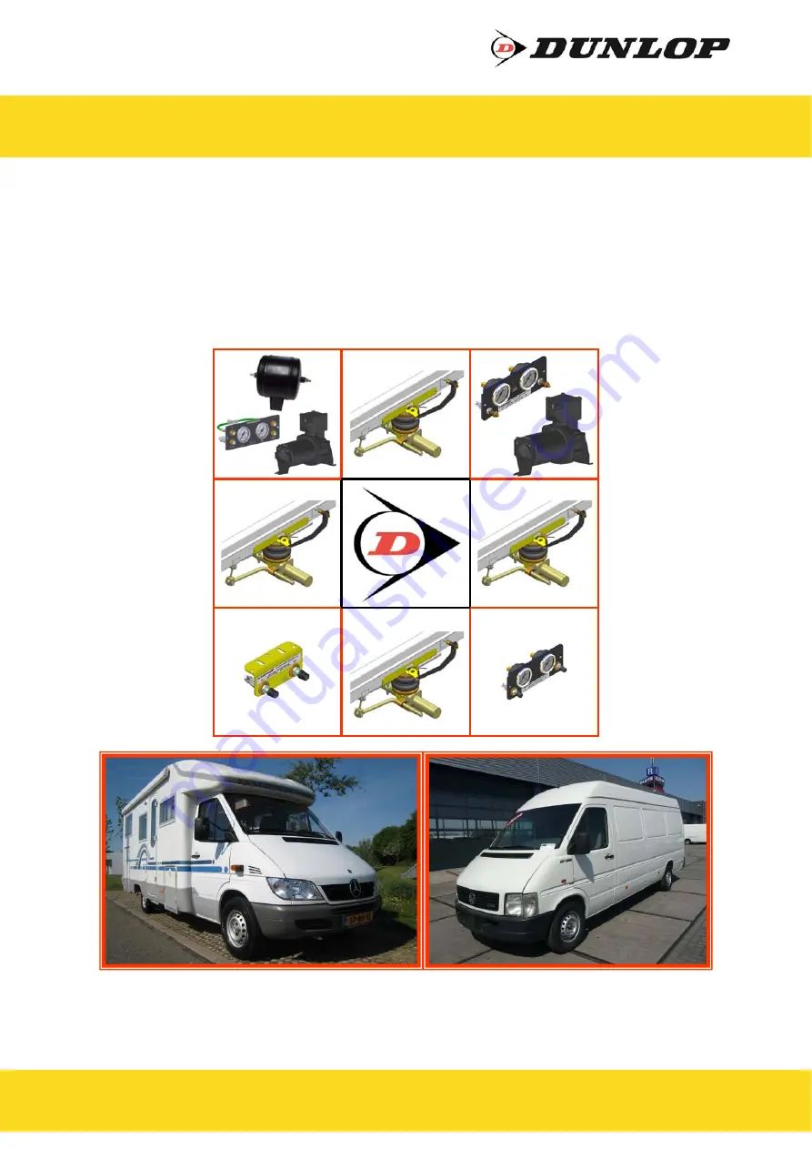
Auxiliary Air Suspension
November 2018
Installation Manual
DUNLOP and the Flying D Device are trademarks of Dunlop International Group and are used under license by DSC Nederland B.V.
L.312.C.M
Mercedes Benz Sprinter 200/300 Series (1995—2006)
Volkswagen LT 28-35 (1995—2006)


