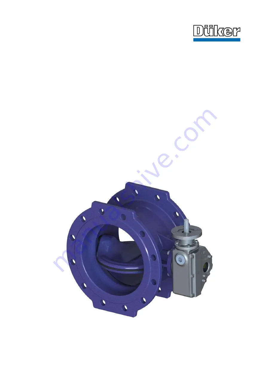
background image


Issue 03 

Düker GmbH 

– www.dueker.de 

page 1


Operating Instructions


Resilient Seated Butterfly Valves  


Type 4510 double flanged  
for water/ gas (PN 10/ 16/ 25)  

 
Item no. of the operating instructions: 764848 Issue


03, 2018

, 19


pages 

Specifications subject to change without notice 


Содержание 4510 Series

Страница 1: ...de page 1 Operating Instructions Resilient Seated Butterfly Valves Type 4510 double flanged for water gas PN 10 16 25 Item no of the operating instructions 764848 Issue 03 2018 19 pages Specifications subject to change without notice ...

Страница 2: ... 5 Installation into the pipeline 6 5 1 General information 6 5 2 Operational steps 7 6 Functional description 7 7 Drawing and parts list 8 7 1 Drawing 8 7 2 Part list 9 8 Operation 10 9 Troubleshooting 12 10 Service and maintenance 13 10 1 Maintenance 13 10 2 Replacing the profile sealing 13 10 3 Adjusting the retaining ring 16 10 4 Tightening torque gear flange 17 10 5 Tightening torque blind pi...

Страница 3: ...on of the valve and the accessories supplied improper operating or operating conditions acts of god To control in continuous operation shut off valves are not usable Cavitation is definitely to be avoided 2 Safety precautions 2 1 General safety instructions The safety regulations applicable to valves are the same as those for the pipeline in which they are installed These instructions only specify...

Страница 4: ...ent can endanger life and limb and cause damage to the piping system The valve must be properly installed in the pipeline In the pipeline the usual flow velocities e g according to EN 1074 1 2 5 5 m s for liquids must not be exceeded in continuous service Abnormal operating conditions such as vibrations water hammers erosion cavitation and greater fractions of solids in the medium especially weari...

Страница 5: ...a very short time This is why the openings are sealed with protective caps Valves must be stored in darkened rooms in their original packaging with the protective caps In the event of storage over an extended period of time the storage location should be frost protected cool dry dark and free of dust Alternatively the valves may also be packed in or der to fulfill these conditions The valve should...

Страница 6: ...the manufacturer Elastomer gaskets according to the DVGW Guidelines W 270 are recommended preference is to be given to flange seals with a metal core accord ing to EN 1514 Part 1 The same instructions apply to the installation of Düker butterfly valves in a pipe as for the connection of pipe elements according to EN 1092 and BS standards It is assumed that the corresponding instructions are known ...

Страница 7: ...rds only original Düker original spare parts may be installed When pushing the valve and the seals into an installed pipe the distance between the pipe ends must be that all connection faces and seals remain undamaged The gap should not be larger than necessary to ensure no additional stresses in the pipe during installation The valve must be installed stress free 6 Functional description The butt...

Страница 8: ...Issue 03 Düker GmbH www dueker de page 8 7 Drawing and parts list 7 1 Drawing ...

Страница 9: ...on Head Screw 5 Shaft 20 Washer 6 Non Drive Shaft 21 Threaded Sleeve lower part 7 Bearing Side A 22 Threaded Sleeve upper part 8 Bearing Side B 23 Grub Screw 9 Profile Seal 24 O Ring 10 Blind pin 25 Straight Pin 11 Disk for Blind pin 26 Washer 12 Sealing Ring 27 Countersunk Screw 13 O Ring 28 Countersunk Screw 14 Seal 29 Countersunk Screw 15 Connection Ring 30 Circlip ...

Страница 10: ...Issue 03 Düker GmbH www dueker de page 10 8 Operation butterfly valve with hand wheel butterfly valve with electric actuator ...

Страница 11: ...ype AUMA Reduction Gear Type Turns for OPEN CLOSE MT nom Gear Input Nm AUMA Actuator Type 100 10 16 SK I B F10 27 30 SA 07 6 25 125 10 16 25 150 10 16 25 200 10 SK II B F12 16 25 40 250 10 16 25 300 10 50 16 25 350 10 60 16 25 SK III B F16 31 80 SA 10 2 400 10 SK II B F12 27 60 SA 07 6 16 SK III B F16 31 80 SA 10 2 25 450 10 16 25 500 10 110 16 25 SK IV B F30 43 600 10 SK III B F16 31 100 16 SK IV...

Страница 12: ...y be installed If it is determined after removal that the housing and or internal parts are not sufficiently resistant to the medium the manufacturer DÜKER should be contacted Dysfunction Remove and inspect the fitting If the valve is damaged Repair is necessary Request replacement parts and required instructions from DÜKER The valve is sealed by O rings Before the blind pin or the connecting ring...

Страница 13: ...ice and maintenance 10 1 Maintenance It is recommended to operate fittings that remain permanently in one position three to four times a year 10 2 Replacing the profile sealing Mark the positon of the retaining ring 4 to the disc 3 yellow line 4 3 3 2 ...

Страница 14: ...GmbH www dueker de page 14 Loosen the countersunk screws 27 of the retaining ring when the valve is closed Leave grub screws 23 untouched because they reproduce the tensioned position of the profile sealing 27 33 23 3 ...

Страница 15: ...e profile sealing 9 remove soiling in sealing area Check the exact location of the profile sealing 9 in the retaining groove Fill threaded holes for the countersunk screws 27 with glass adhesive Tighten the countersunk screw 27 on the retaining ring 4 to the specified torque Move the valve disc 3 to the CLOSED position Pressure test depending on the pressure level 4 3 9 used 3 2 9 new 27 2 ...

Страница 16: ...rface of the butterfly disc 3 10 3 Adjusting the retaining ring The retaining ring 4 can be adjusted in the CLOSED position of the butterfly valve For this purpose the grub screws 26 are released while the countersunk screws 25 are tensioned with a permissible torque After this procedure the grub screws 26 are to be fixed by turning clockwise To ensure proper function and compliance with drinking ...

Страница 17: ...Issue 03 Düker GmbH www dueker de page 17 10 4 Tightening torque gear flange Gearbox attachment A2 70 und A4 70 Dimension M10 M12 M16 M20 M24 Permissible torque Nm 35 150 180 290 500 ...

Страница 18: ... pin 10 6 Tightening torque retaining ring Screws for fixing the blind pin A2 70 und A4 70 Dimension M10 M12 M16 M20 M24 Permissible torque Nm 35 150 180 290 500 Screws for fixing the retaining ring Dimension 100 300 350 600 700 1200 Permissible torque Nm 7 10 10 12 12 15 ...

Страница 19: ...zed exclusively for the purpose of ensuring the correct installation and operation of the Düker product treated in the document For all other purposes distribution reproduction and utilization of the contents also in excerpts is prohibited Offenders will be held liable for the payment of damages All rights reserved in the event of the grant of a patent utility model or design ...

Отзывы: