5
ENGLISH
L2000631 Installation guide for DucoBox Focus (Revision J | 17.07.2019)
04
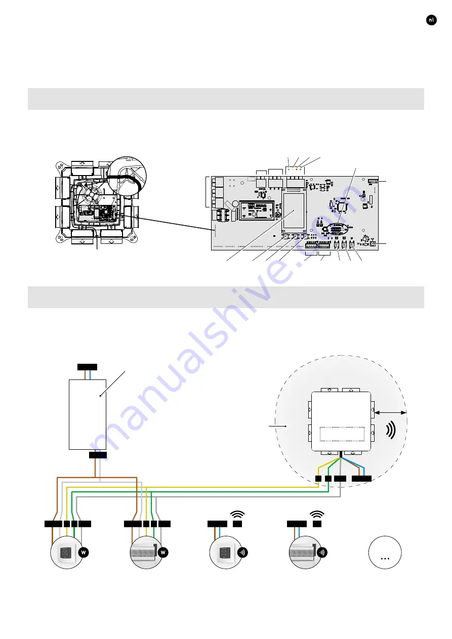
Wiring
04.A
Connector & buttons
Strain relief
It is mandatory to place the power supply cable in the slot provided, as shown in the drawing, before powering up the DucoBox�
04.B
Cabling diagram
The DucoBox Focus is able to communicate with Duco slave components via a wireless (RF) or wired link� Both types of communi-
cation can be combined in one system� Communication with non-Duco components is possible via the Switch Sensor or one of the
connections on the optional Communication Print (see page 8)�
RF
RF
Wired*
RF
24 VDC
24 VDC
24 VDC
230 VAC
230 VAC
A
A
B
B
GND
GND
B
A
GND
POWER
SUPPLY
User controller
User controller
Max 99 Wired
+ 25 RF
Tronic vent
Tronic vent
230 VAC
230 VAC
DucoBox
Focus
RF obstacle-free zone
Do not place any obstacles causing RF interference
or other devices with an RF connection within a
radius of at least 30 cm around the RF component�
We take these to include items such as washing
machines, tumble dryers, ironing boards, etc�
The power supply can be determined depending on
the technical data sheet for each component (see
www�duco�eu)� The power rating of all individual
components needs to be checked� The power supply
needs to be capable of coping with the sum of these
requirements with a cable length not exceeding 300 m�
≥ 30 cm
* Use a screened solid-core cable not exceeding 300 m in length, with 5 cores 0�8 mm each�
Valve 2
Valve 1
HIGH
DOWN
LOW
ENTER
INST
UP
Power
230 VAC
Fan
Duco
Wired
Antenna
Duco
Network
Tool
Switch
Contact
(n132)
GND
B
A
Blue Yellow
Red
White
Connector for
Communication Print
Display
PE
N
L
Illustrations and connections may vary depending on product configuration�
Incorrect connection or failure to follow the instructions may result in
damage to the connected devices�


