dtec DYNertia3 Скачать руководство пользователя страница 9


www.dtec.net.au 

9


DYNertia3 Quick Start (Inertia- Chassis type) 


Basic Hardware Settings 

 
As an example of a basic test ‘Run’ we will test a motorbike, we will do the test in 4

th

 gear and save the results for future 

reference.  
 
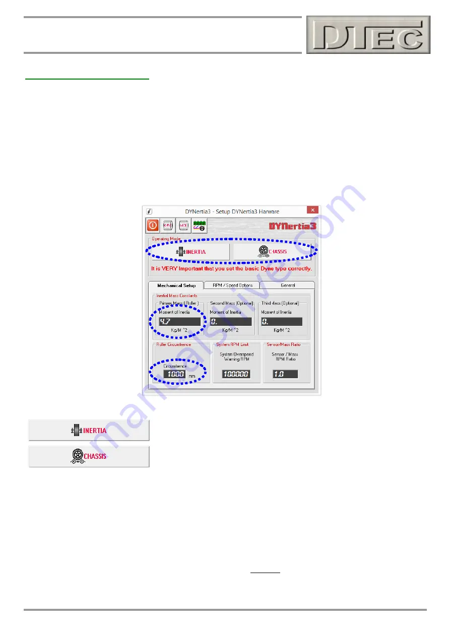
This example Dyno has roller of 1000mm circumference and an inertia factor of 4.7 kg/m² (your dyno’s inertia value can 
be calculated by pressing the ‘MOI” button in Setup/Hardware and adjusted later if required). DYNertia sensor is picking 
dyno RPM up from the roller. Leave program settings are in their default position. 


First time use, Hardware setup 

At the top Left of the Window 

you will find the menu options. Under the menu option “Setup” you will find “Hardware”.  


Ensure ‘INERTIA’ mode is selected. 
 
 
Select ‘CHASSIS’ dyno type. 


Roller Circumference:

  Enter roller circumference (1000mm in this example) to ensure speeds displayed (kph/mph) are 

correct 
 

Inertia Mass:

  Enter 

the dyno’s MOI (Moment Of Inertia) inertial value, 4.7 for this example. 

As mentioned above, your dyno’s inertia value can be calculated by pressing the ‘MOI” button at the top of the window. 


#

 Leave other settings in their default position as shown, especially DO NOT choose any alternative RPM source. 

Содержание DYNertia3

Страница 1: ...The creators and distributors of this software shall not be liable for any loss damages or costs arising out of but not limited to lost profits or revenue loss of use of the software loss of data or...

Страница 2: ...ains basic information for your Inertia dyno chassis type This is a brief overview of some main operations it builds the base that will allow understanding of the features explained in the main DYNert...

Страница 3: ...Displaying Engine RPM One Method 11 Performing a Basic Inertia Test Run 12 You are now ready to perform a test 12 Observing the engine data during a test 13 Viewing Loading of Runs Graph Window 14 Lo...

Страница 4: ...DYNertia Sensor and Magnet Mount the sensor system to detect the rotation of the roller shaft Note Do not mount the magnet at the outside diameter of the dyno roller shaft as the centrifugal forces w...

Страница 5: ...possible Route all cables as far as possible away from the engine and any electric motors such as cooling fans and keep the controller and PC at a distance Coil any spare cable up neatly at the PC Kee...

Страница 6: ...correct dyno operation is confirmed and some trial runs have actually been done Do not connect any sensors to input terminals Do not connect anything to the RPM Adapter input including the RPM adapte...

Страница 7: ...into another USB port you may need to re link This Window will also appear whenever DYNertia3 is started and the control units are not connected powered or Linked Pressing the Continue OFFLINE button...

Страница 8: ...splayed on the second monitor instead and replaced with the test comments field also found in View menu The GRAPH Window displays the Power and Torque as traces that can be overlayed and analysed Trac...

Страница 9: ...Leave program settings are in their default position First time use Hardware setup At the top Left of the Window you will find the menu options Under the menu option Setup you will find Hardware Ensur...

Страница 10: ...e to do a quick function check Open the main DYNO Window and observe the RPM gauge while vehicle is turning the dyno at this stage it will show the shaft RPM at the sensor not engine It is often worth...

Страница 11: ...w visible Ride the bike until the bikes tacho matches the Engine Target RPM in your test gear 4000 RPM in this example shown alter this set point if RPM not suitable for your vehicle then simply press...

Страница 12: ...RPM you wish to test to set the minimum RPM to just above the RPM you start testing at Check that Current Ratio is set to Ratio 4 assuming this is the button we used previously to teach a ratio in thi...

Страница 13: ...data to display on secondary screens Due to limited screen space with only a single monitor the data is displayed as shown to the Left There are chart recorders and gauges for RPM whilst the 4 data c...

Страница 14: ...ctually 10 using secondary screen To temporarily hide any trace from view click on its Check Box to view associated data and notes click on the button Load runs To load a new Run into the graph for vi...

Страница 15: ...YNertia3 files on your PC Note If you are selecting a Folder that you wish to use to save runs into then press the File Storage icon top LH It will be this Folders content that is shown when then savi...

Страница 16: ...indow The coloured cursor matches selected trace will indicate via the gauges the values present Clicking in the graphs Right hand side where the scales are will display the floating data Window as sh...

Страница 17: ...xplained Note Windows may only be relevant if the required data was collected e g Lambda deviation Window is only valid if you are recording Lambda into a data channel Torque analysis Area under curve...

Страница 18: ...n greatly speed testing AutoInc is to automatically increment a file name rather than re typing it in The menu Help Shortcut Keys lists the shortcut keys including those that are user assigned e g PgU...

Страница 19: ...sive end Note Personally I would set the max RPM lower to prevent the trace from dropping away and risking doubling back under NOT OK Both these traces are running back under themselves at the test en...

Страница 20: ...PM adapter which is used to derive torque from the power and is used for the X axis graph scale RPM If you display the same data above in speed mode kph on X axis and not RPM mode it will remove the i...

Отзывы: