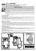
Installation Instructions
LC-103PIMSK
Professional Passive Infrared & Microwave Detector
with Anti-Mask with Pet Immunity
The detector provides an analysis of environmental conditions through the entire movement speed frequency spectrum,
allowing focus on intruders and eliminating environmental factors of false alarms. The spectrum analysis is embedded
in the VLSI based electronics of the detector assuring high reliability and trouble free operation. Unique function - anti-
mask - guarantees detector protection from non desirable approach and any kind of masking beginning from the distance
0.8m and closer.
As the LC-103PIMSK is a combined technology (PIR & microw ave) an alarm signal relay activation occurs only when signals
from both sensors (PIR & MW) are present at the same time. The effective detection range is the range of which the patterns
(PIR & MW) are intersected. The GAIN potentiometer adjustment changes the MW signal intensity so that the effective pattern
will be scaled.
Unique function - anti-mask - guarantees detector protection from non desirable approach and any kind of masking beginning
from the distance 0.8m and closer.
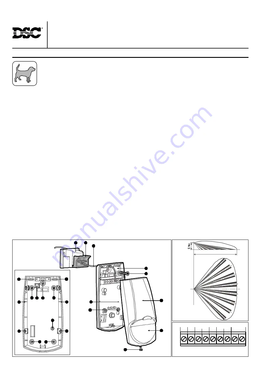
FIG 1
- Knockout h oles
C
C
A
B
B
B
B
A
A
D
D
C
C
C
TYPICAL INSTALLATION
Select mounting location
C hoose a location most likely to intercept an intruder. (Our recommendation is a corner installation). See detection pattern (Fig.3). The quad-
element high quality sensor detects motion cr os sing the beam; it is slightly less sensitive detecting motion tow ard the detector.
The LC-103PIMSK performs best when provided with a constant and stable environment.
Avoid The Following Locations:
*
Facing direct sunlight.
*
Facing areas that may change temperature rapidly.
*
Areas where there are air
duc ts or s ubs tanti al air flow s.
T he LC - 103PIMSK perform s better w hen pr ovided wi th a c onstant and stable env ironment.
N O TE :
LC -103 PIMSK br eaks off Anti-M ask alar m s ignal only after rec eivi ng s ignal from PIR ’ but not l essthan 30 s ec.
MOUNTING DETECTOR BASE
1.
To remove the front cover, unscrew the holding screw and gently raise the front cover. (Fig.2-11)
2.
To remove the PC board, carefully unscrew
the holding screw located on the PC board.(Fig.2-9)
3.
Break out the desired holes for proper installing (Fig.1-B or C).
4.
The circular and
rectangular indentations at the bottom base are the knockout holes for w ire entry. You may also use mounting holes that are not in use for running
the wiring into the detector.(For option with bracket - lead wire through the bracket, Fig2-7)
5.
Mount the detector base to the wall, corner or
ceiling. (For option w ith bracket install bracket).(Fig.6,Fig.7)
6.
Reinstall the PC board by fully tightening the holding screw. Connect wire to
termi nal block .
7.
R epl ac e the cov er by inserting it back in the appropri ate closing pi ns and s crew i n the holding sc rew.
DETECTOR INSTALLATION
Terminal Block Connections
(See Fig.4)
Terminals 1 & 2 - Marked “T1,T2” (TAMPER)
If a Tamper function is required connect these terminals to a 24-hour normally closed protective
zone in the control unit. If the front cover of the detector is opened, an immediate alarm signal w ill be sent to the control unit.
Terminals 3 & 4 - Marked “A M: N C, C ”
These are the output relay Anti Mask contacts of the detector. Connect to a normally closed zone in
the control panel.
Terminal 5 - Marked “EOL” -
End of line option.
Terminals 6 & 7 Marked “PIR: NC, C”
These are the output relay PIR contacts of the detector. Connect to a normally closed zone in the control
panel.
Terminal 8 - Marked ”-” (GND)
C onnect to the negative Voltage output or ground of the control panel.
Term in al 9 - Marked “+” ( +12V)
C onnect to a positive Voltage output of 8.2 -16Vdc source (usually from the alarm control unit).
FIG 2
- Detector Installa tion
FIG 4
- Terminal block
11
6
5
8
4
10
9
1
3
7
1
2
3
4
5
6
7
8
9
- 12V +
T1
EOL
T2
C
NC
C
NC
AM
PIR
FIG 3
- Lens pattern
15m


