DRUCKER DIAGNOSTICS
SM013
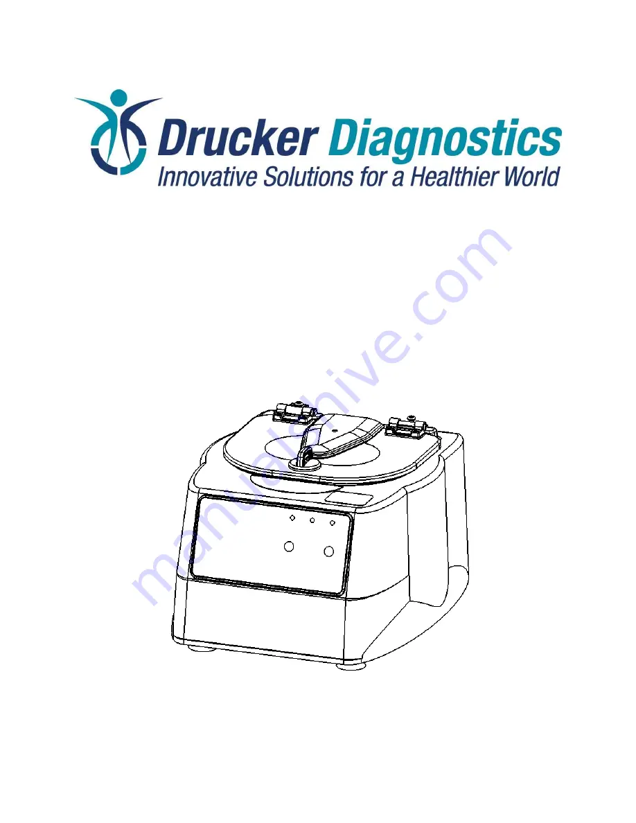
MODEL APEX 6 SERVICE MANUAL
REV: C
1
200 Shadylane Drive
Philipsburg, PA 16866
Phone: (814) 342-6205
Fax: (814) 342-4510
www.druckerdiagnostics.com
Service Manual
Model Apex 6 Centrifuge
Страница 1: ...RUCKER DIAGNOSTICS SM013 MODEL APEX 6 SERVICE MANUAL REV C 1 200 Shadylane Drive Philipsburg PA 16866 Phone 814 342 6205 Fax 814 342 4510 www druckerdiagnostics com Service Manual Model Apex 6 Centrifuge ...
Страница 2: ...EL APEX 6 SERVICE MANUAL REV C 2 CONTENTS 1 PREFACE 3 2 GENERAL DESCRIPTION OF MAJOR COMPONENTS 3 3 WARRANTY INFORMATION 3 4 SPECIFICATIONS 3 5 TROUBLESHOOTING 4 6 SERVICE INSTRUCTIONS 5 7 ASSEMBLY DRAWINGS 9 8 REVISION HISTORY 13 ...
Страница 3: ...he PCB is the microcontroller based control center of the centrifuge All control signals are generated in the PCB 2 3 Lid Locking Tray Assembly The lid tray assembly contains a solenoid and limit switch that are used to determine the state of the lid Open or Closed and to keep the lid locked during centrifugation cycles 2 4 Rotor The centrifuge rotor is the main component that spins in the centrif...
Страница 4: ...nt in the rotor whether loaded or empty Debris lodged within the rotor or tube carriers Carefully inspect all rotor pockets tube holders and crevasses for debris Centrifuge housing is loose Requires service Missing damaged feet Requires service Motor failure Requires service Rotor windshield damage Requires service Rotor damaged Replacement required PROBLEM POSSIBLE CAUSE SOLUTION Rotor does not s...
Страница 5: ...and the tube numberings 1 through 6 with the windshield cover e Tighten the rotor screw with a 1 8 hex driver to 2 0 Nm 6 3 Maintaining the Rotor a Keep the rotor clean any corrosive materials must not be allowed contact with the rotor and should be cleaned immediately b The rotor should be checked periodically for signs of wear c Remove the rotor from service if any of the following are found cra...
Страница 6: ...move the lid tray wire harness from the PCB f Use a 2 Phillips screwdriver to remove the two lid tray screws inside the cabinet g To install the lid tray reverse steps F through C above h Complete the installation by gently plugging the lid tray wire harness into the PCB header J2 6 8 Replacing the PCB a The PCB is accessible once the cabinet has been removed Make certain that all wire harnesses h...
Страница 7: ...the guard bowl with the wire harness positioned as described above d Secure the motor to the guard bowl using four 8 washers and four 8 Nylok nuts e Drive the four 8 Nylok nuts onto the motor studs with an 11 32 nut driver f Turn the guard bowl assembly upside down g Place the base assembly onto the guard bowl h Ensure the motor wires pass through the notch in the bottom rim of the guard bowl i En...
Страница 8: ...d Connect the power supply harness connector to J17 e Connect the grounding strap to the base assembly using a 11 16 nut driver f Carefully place the cabinet onto the base taking care not to pinch any wires between the two g Complete the assembly by replacing the nine screws and three washers using a 2 Phillips screwdriver ...
Страница 9: ...DRUCKER DIAGNOSTICS SM013 MODEL APEX 6 SERVICE MANUAL REV C 9 7 ASSEMBLY DRAWINGS 7 1 FINAL CENTRIFUGE ASSEMBLY 7 1 1 Reference drawing 01 076 109 000 ...
Страница 10: ...DRUCKER DIAGNOSTICS SM013 MODEL APEX 6 SERVICE MANUAL REV C 10 7 2 CABINET ASSEMBLY 7 2 1 Reference drawing 02 002 0 0043 ...
Страница 11: ...DRUCKER DIAGNOSTICS SM013 MODEL APEX 6 SERVICE MANUAL REV C 11 7 3 LOWER ASSEMBLY 7 3 1 Reference drawing 02 003 0 0105 ...
Страница 12: ...DRUCKER DIAGNOSTICS SM013 MODEL APEX 6 SERVICE MANUAL REV C 12 7 4 MOTOR ASSEMBLY 7 4 1 Reference drawing 02 005 1 0010 ...
Страница 13: ...DRUCKER DIAGNOSTICS SM013 MODEL APEX 6 SERVICE MANUAL REV C 13 8 REVISION HISTORY Revision Date Details of Change A 11 17 2015 Original Issue DR 4324 B 7 11 2018 DR 5998 ...