WJ-8611 DIGITAL VHF/UHF RECEIVER
CIRCUIT DESCRIPTIONS
5-7
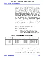
Table 5-2. 1st LO Synthesizer Tuning Bands
Band
Tuned Frequency Range
1st LO Frequency Range
Switching Test
Point
1
20.0000 - 192.5000 MHz
1370.0 - 1542.5 MHz
TP 13
2
195.0000 - 400.0000 MHz
1545.0 - 1750.0 MHz
TP 12
3
402.5000 - 610.0000 MHz
1752.5 - 1960.0 MHz
TP 11
4
Not Used
TP 14
5
612.5000 - 822.5000 MHz
1962.5 - 2172.5 MHz
TP 16
6
825.0000 - 1000.0000 MHz
2175.0 - 2350.0 MHz
TP 15
The frequency of the 1st LO synthesizer is controlled by a tuning voltage
produced by the synthesizer’s phase detector. It is the result of comparing
a frequency divided sample of the VCO output frequency with a fixed
reference. The 10 MHz reference signal entering the assembly at terminal
E2 is divided by a factor of eight to produce a 1.25 MHz square wave at
the phase detector reference input (TP23). When the synthesizer is locked
on frequency, the
÷
N and
÷
A counters divide the VCO frequency sample
down to equal the reference frequency. This is visible at TP4 as a series of
voltage spikes at a 1.25 MHz rate. The results of this frequency
comparison produce the tuning voltage. At TP24, the tuning voltage will
range from approxi1.5 to +16 V, depending on where in the active
VCO band the oscillator is tuned. If the synthesizer fails to lock on
frequency, this voltage will swing to its minimum or maximum extreme
(0 V or +22V).
The operating power for the 1st LO/1st Converter PC Assembly (A3A1) is
supplied through connector P1 from the 2nd LO/2nd Converter PC
Assembly (A3A2). The input voltages are +5.5 Vdc at pins 2 and 3,
+24 Vdc at pin 4, +13 Vdc at pin 6, and -13 Vdc at pin 7. These voltages
are routed through regulation circuitry in the assembly and are distributed
to the various circuits in the assembly.
5.2.2 PART 482903-1 2ND LO/2ND CONVERTER PC ASSEMBLY (A3A2)
The functional block diagram of the 2nd LO /2nd Converter PC Assembly
(A3A2) is illustrated in
. Refer to this illustration for the
The 2nd LO/2nd Converter PC Assembly (A3A2) accepts the 1350 MHz
IF from the 1st LO/1st Converter PC Assembly (A3A1) and performs the
2nd and 3rd stages of signal conversion to produce two IF outputs. The
wideband 21.4 MHz Signal Monitor Output (J2) supplies a 50-ohm output
to the rear panel for use with an external signal monitor or spectrum
display unit. Its level is approximately 14 dB greater than the receiver’s
RF input level. The 250 kHz IF output (P1) provides a 200 kHz wide IF
signal to the Digital Control PC Assembly (A2) to be digitized prior to
Courtesy of http://BlackRadios.terryo.org
Содержание WJ-8611
Страница 3: ...A B blank Courtesy of http BlackRadios terryo org...
Страница 4: ...THIS PAGE INTENTIONALLY LEFT BLANK Courtesy of http BlackRadios terryo org...
Страница 19: ...1 i SECTION 1 GENERAL DESCRIPTION Courtesy of http BlackRadios terryo org...
Страница 20: ...1 ii THIS PAGE INTENTIONALLY LEFT BLANK Courtesy of http BlackRadios terryo org...
Страница 28: ...WJ 8611 DIGITAL VHF UHF RECEIVER 1 8 GENERAL DESCRIPTION NOTES Courtesy of http BlackRadios terryo org...
Страница 29: ...2 i SECTION 2 INSTALLATION Courtesy of http BlackRadios terryo org...
Страница 30: ...2 ii THIS PAGE INTENTIONALLY LEFT BLANK Courtesy of http BlackRadios terryo org...
Страница 47: ...3 i SECTION 3 LOCAL OPERATION Courtesy of http BlackRadios terryo org...
Страница 48: ...3 ii THIS PAGE INTENTIONALLY LEFT BLANK Courtesy of http BlackRadios terryo org...
Страница 84: ...WJ 8611 DIGITAL VHF UHF RECEIVER 3 36 LOCAL OPERATION NOTES Courtesy of http BlackRadios terryo org...
Страница 85: ...4 i SECTION 4 REMOTE CONTROL Courtesy of http BlackRadios terryo org...
Страница 86: ...4 ii THIS PAGE INTENTIONALLY LEFT BLANK Courtesy of http BlackRadios terryo org...
Страница 119: ...5 i SECTION 5 CIRCUIT DESCRIPTIONS Courtesy of http BlackRadios terryo org...
Страница 120: ...5 ii THIS PAGE INTENTIONALLY LEFT BLANK Courtesy of http BlackRadios terryo org...
Страница 142: ...WJ 8611 DIGITAL VHF UHF RECEIVER 5 22 CIRCUIT DESCRIPTIONS NOTES Courtesy of http BlackRadios terryo org...
Страница 143: ...6 i SECTION 6 MAINTENANCE Courtesy of http BlackRadios terryo org...
Страница 144: ...6 ii THIS PAGE INTENTIONALLY LEFT BLANK Courtesy of http BlackRadios terryo org...
Страница 167: ...7 i SECTION 7 REPLACEMENT PARTS LIST Courtesy of http BlackRadios terryo org...
Страница 168: ...7 ii THIS PAGE INTENTIONALLY LEFT BLANK Courtesy of http BlackRadios terryo org...
Страница 243: ...A i APPENDIX A 8611 SM SIGNAL MONITOR OPTION Courtesy of http BlackRadios terryo org...
Страница 244: ...A ii THIS PAGE INTENTIONALLY LEFT BLANK Courtesy of http BlackRadios terryo org...
Страница 267: ...FP i FOLDOUTS Courtesy of http BlackRadios terryo org...
Страница 268: ...FP ii THIS PAGE INTENTIONALLY LEFT BLANK Courtesy of http BlackRadios terryo org...
Страница 298: ...Courtesy of http BlackRadios terryo org...
Страница 300: ...Courtesy of http BlackRadios terryo org...
Страница 301: ...Courtesy of http BlackRadios terryo org...


