background image

DRS-M600 Parachute manual

Document revision 1.1, November 14, 2019

Содержание DRS-M600

Страница 1: ...DRS M600 Parachute manual Document revision 1 1 November 14 2019...

Страница 2: ...ms GmbH its subsidiaries the directors employees and agents cannot be held liable for the use of and reliance of the opinions esti mates forecasts and findings in these documents We recommend that you...

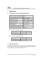
Страница 3: ...er of deployments 10 Minimum deployable altitude 58 90 m Results tested at 11 50 kg take off weight Average descent rate 3 92 m s 14 1 km h 8 70 mph Average impact energy 88 3 J 65 0 ft lb Results tes...

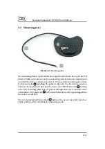
Страница 4: ...icture 1 and will store the parachute on the DJI Matrice M600 pro while flying It is made out of carbon fiber composites and uses elastic rubber bands 1 to deploy the parachute automatically in case o...

Страница 5: ...op of the mounting plate there is a bayonet joint 1 including five golden stripes for the electrical connection between the deployment unit and the motor cut off PCB The wire 2 coming out of the mount...

Страница 6: ...y via the remote controller from the pilot in command This PCB also forces the landing gear coming down after the de ployment to safe the payload located underneath when touching the ground Therefor t...

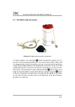
Страница 7: ...y around the parachute canopy when getting loaded into the deployment container to secure a fast and reliable deployment At the end of the leash is a metal hook to connect it to the UAVs frame Also in...

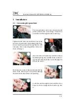
Страница 8: ...tion of anything mounted on top like the GPS antennas After connecting all three arms con tinue with step 3 2 3 After all cords are hooked up with the arms of the M600 pick up the small lid of the co...

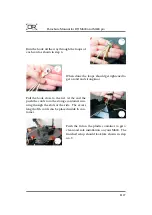
Страница 9: ...a solid and strong knot Pull the hook close to the lid At the end the push the cords into the storage container run ning through the slots at the side The excess length of th cords can be placed insi...

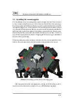
Страница 10: ...ay from critical components like the GPS antennas As shown in picture 5 the plate is mounted above battery num ber six because the antenna is located between battery two and three In case of a parachu...

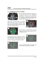
Страница 11: ...minals which lock the red positive and black nega tive power supply cables for the motors Only pull out the red wires while you leave the black ones at it s original positions 2 3 Place the motor cut...

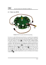
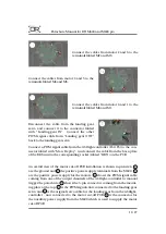
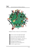
Страница 12: ...able from the base plate of the DRS unit to the corresponding socket labled DRS on the PCB An overall view of the motor cut off PCB installation is shown in picture 6 1 are the ground and 2 the positi...

Страница 13: ...o connect to the negativ power supply 2 Screws to connect to the positiv power supply 3 Positive power cables connected to the motors 4 PWM signal for manual triggering connected to A3 5 Interface con...

Страница 14: ...at the top to the motor cut off PCB at the bottom Beside the electrical installation the A3 has to get configured as well Picture 7 PWM wire to manually deploy the parachute To enable the manual depl...

Страница 15: ...Parachute Manual for DJI M600 and M600 pro Picture 8 Assigning port F3 to the shutter trigger channel Picture 9 Setting shutter default and trigger PWM value 14 27...

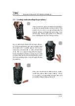
Страница 16: ...Use a solid object which fits the inner diame ter of the deployment unit and is longer then the whole unit A plastic pipe is very conve nient but a small bottle of water should also work Use it to pus...

Страница 17: ...end and remove the other one when the parachute is half inside of the tube 4 5 Push in the parachute covered by the plastic sheet with the spiky end first The spikes are essential to prevent the parac...

Страница 18: ...00 Place the container on the mounting plate with the small pike arrow at the bottom pointing towards the open padlock symbol After push ing it down a bit you should be able to twist it clock wise unt...

Страница 19: ...ree color RGB Red Green Blue LED Light emitting diode to inform the pilot about the internal system status as described in table 1 Color Type Description Blue Flashing System initializing Blue Solid S...

Страница 20: ...longer period of time we rec ommend to take out the parachute canopy and remove the tension from the deployment unit Always store the system in a dry environment to prevent moisture accumulating insid...

Страница 21: ...the status LED will blink in violet color which will take about 5 to 10 seconds After a successful update the LED will blink green In case of any error the LED will blink red 5 2 Configuration The beh...

Страница 22: ...ceeds set value Set to zero to disable this feature MOTOR_OFF_DELAY 0 0 10000 ms Delay parachute deployment for configured time This refers to manual and automatic deployment Table 2 Available paramet...

Страница 23: ...protection foil The parachute is fully loaded inside of the tube and no parachute fabric is protruding The deployment container is twisted to its locked position Proper connection of the parachute wit...

Страница 24: ...year which include the following steps Repacking the parachute Replacing the plastic protection foil Replacing the rubber bands Replacing the four leashes which connect the parachute with the drone Th...

Страница 25: ...lls on each side The wires have to be in the middle Use a strip with a width of 140 mm which acts as a helping tool to fold the parachute to the cor rect size 3 4 Pull the parachute fabric over the st...

Страница 26: ...es of the parachute using your pointing and little finger You should start where the hook is connected and end close at the fabric 7 8 Place the whole packet of wires into the last area of the parachu...

Страница 27: ...nual for DJI M600 and M600 pro 10 Take care the parachute is fully wrapped in the plastic foil and no fabric or wire is protrud ing This is essential to preventing getting the parachute stuck when dep...

Страница 28: ...Parachute Manual for DJI M600 and M600 pro 9 Document revision Revision Date Author s Description 1 0 September 23 2019 MMa MMo created 1 1 November 14 2019 Manninger New motor cut off PCB v0 5 27 27...

Отзывы: