6
7.4.
USE
•
Check the setting data indicated on the control panel (if present).
•
Press the start button on the machine where the pump is connected.
•
Ensure that the pump starts.
•
Ensure the adequate lubrication of the machine (if there are doubts on correct operation, you can contact the Dropsa
S.p.A. Technical Office and ask for the testing procedure).
8.
PROBLEMS AND SOLUTIONS
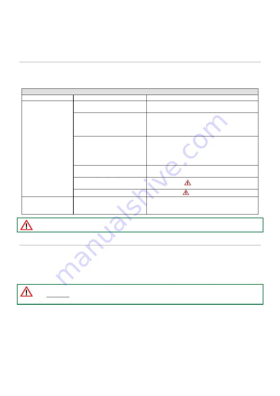
Below is a troubleshooting table where the main faults, probable causes and possible solutions to be carried out immediately
are indicated (contact Dropsa).
In the event of doubts and/or irresolvable problems, do not search for the fault disassembling parts of the pump, but rather
contact the Dropsa Technical Office.
TROUBLESHOOTING TABLE
FAULT
CAUSE
REMEDIAL ACTION TO BE TAKEN
The pump does not
dispense lubricant or
does not dispense the
prescribed quantity.
The lubricant in the reservoir is
below the minimum level.
Top up the reservoir without exceeding the MAX level line.
The pump control solenoid valve
does not vent.
Ensure that the pump control solenoid valve is a 3-way
valve for single acting pumps or 4-way for dual acting
pumps. Also ensure that the oil in the pump chamber
discharges regularly.
Air bubbles in the lubricant.
Open the bleed valve and activate the pump according to
the manual operating cycle until lubricant comes out of
the connection without any air bubbles. Close the valve.
You can manually press the cartridge itself in order to
favour priming of the pumping unit.
The fittings are loose.
Carefully tighten all the fittings, ensuring that there are
no leaks.
The piston of the pumping element
is worn out.
Replace the piston
.
The delivery valve is blocked.
Replace the valve
.
The pump does not
dispense lubricant at the
prescribed pressure.
The pressure regulation of the
incoming control oil is incorrect.
Appropriately regulate the oil pressure as prescribed by
the general characteristics and bearing in mind the
compression ratio.
Operation may only be carried out by Dropsa specialised personnel.
9.
MAINTENANCE PROCEDURES
The pump does not require special tools for any check and/or maintenance operations. In any case, it is recommended to use suitable
equipment and personal protective equipment (gloves, protection goggles, etc.) that in good condition in accordance with applicable
regulations to avoid injury or damage to parts of the pump.
The unit has been designed and built in such a way that it requires a minimum level of required maintenance. Nevertheless, it is
recommended to always keep the body of the equipment clean and periodically check the tube joints in order to be able to readily
detect any leaks.
ATTENTION: Before any maintenance or cleaning operation, make sure that hydraulic feed and electric power
are disconnected.
9.1.
PUMP DISASSEMBLY
•
Empty the reservoir;
•
Disconnect the piping;
•
Loosen the securing screws;
•
Remove the reservoir, taking particular care for the models fitted with a grease pusher spring (could be loaded);
•
Remove the pump and any filters;
•
Unscrew the hydraulic cylinder from the pump, paying particular attention to the load the spring has;
•
Remove all the other components.
Before reassembling the pump, all the components should be washed with petroleum and lubricated.


