Service Manual
rev 5.0 with software Ind1V022
-
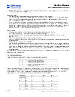
If either of the direction signals S1 or S2 is on, the D2L display shows F6 and driving can begin only after the
direction signals have been off for a while.
Normal operation
-
For the description of the speed reference setting see chapter "Control methods".
-
Hoisting (lowering) starts when switch S1 (S2) closes. Closing the contact ROB2 on A1 energizes K7, which
opens the brake (in model 055 the brake can be controlled also by K71). D2L accelerates according to the
acceleration ramp setting to the selected speed.
-
When the switch S1 (S2) opens D2L stops according to the deceleration ramp setting and the brake closes.
-
R1 dissipates the regenerated energy during lowering periods. The power supply to R1 is controlled by A1. If
the braking resistor fan(s) are included in external resistor unit, they start to operate when power is supplied to
the braking resistors. The cooling continues about 4-5 minutes after electrical braking to ensure that the
temperature of the resistors drops below 150
°
C (302
°
F).
Other features
-
Slowdown limit switches S11 and S21 provide position dependent frequency limiting.
-
Any reason which opens contact RDY, stops the operation of inverter.
-
In case of overload, motor overheating etc. the hoisting can be disabled by cutting the direction signal in
terminal X1:8.
-
Thermistor relay function, which can be used when needed.
-
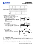
When the stop limit switch S12 or S22 opens, K7 (K71 in model 055F) de-energizes and the mechanical brake
stops the motion.
-
Independent speed supervision unit, SSU
-
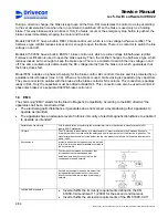
The speed measurement and supervision can be done either with encoder, bearing sensor or proximity switch.
The measured signals are square wave pulses. The frequency of the pulses is proportional to the speed of the
motor and if the frequency is too high, overspeed is detected. If there are no pulses a stall situation is detected.
If the actual speed differs too much from the supply frequency of the motor, the speed difference supervision
stops the motion.
Proximity switch buffer amplifier A5 amplifies the sensor pulses and filters out disturbances. The amplifier
is located close to the sensor.
1.6 Control
methods
There are three different control methods (command modes) available:
1
EP2
Electronic motor potentiometer function.
Stepless control using a 2-step controller.
2
EP3
Electronic motor potentiometer function.
Stepless control using a 3-step controller.
3
MS
Multistep control (4 steps)
The control mode of inverter is selected by parameter P2.1.4. See chapter Control methods. The parameters
assigns digital inputs S1, S2, OK, DIA3-DIA5 and DID1-DID5.It is not possible to chance the functions of the
inputs separately. The state of inputs can be checked from parameters V4.7.12 and V4.7.13. The input
assignment according to the selected mode is explained in the following table.
Control mode
EP EP3
MS
Parameter P2.1.4
1 2
3
Signal Terminal
S1 X1:8
S1
S1
S1
S2 X1:9
S2
S2
S2
OK X1:7
OK
OK
OK
DIA3 X1:10 AP
AP
MS2
DIA4 X1:11 Not
used
HOLD
MS3
DIA5
X1:12
Not used
not used
MS4
7/58
Drivecon Inc. reserves the right to alter or amend the above information without notice.
Содержание D2L
Страница 59: ......


