Service Manual
rev 5.0 with software Ind1V022
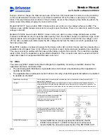
Some problems may occur when using shielded flat cable or in situations where the encoder cable has been
placed too close (< 5cm) to the motor cables and braking resistor cables. Cabling methods and distances
determine the best way to ground the shielded cable; at both ends or only at one end.
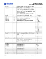
Buffer amplifier pulse output can be measured during driving. If the pulse sequence is not uniform and for
instance longer pulses occur every now and then, the reason may be one of following:
- an incorrect air gap (proximity switch)
- the sensor is not properly on the top of the pulse wheel (proximity switch)
- disturbances are transferred to the sensor cable
- the pulse wheel is faulty
Honeywell 3GT101DC Hall-sensor requires tooth movement past the sensor. A motionless tooth can not
generate a pulse.
3.3.4 Buffer amplifier KAE234
The speed sensor (proximity switch or sensor bearing) is connected to D2L via KAE234 buffer amplifier.
KAE234 must be located near the sensor (usually in the connection box of the hoist or the motor).
Without a buffer amplifier some faulty pulses could activate the speed supervision of D2L. Typically the
problem would be a momentary lack of pulses or oscillations at the sensor output. Usually the noise sensitivity
increases when the sensor temperature rises.
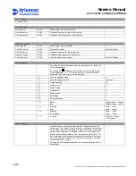
KAE234 connection with sensor bearing.
3
4
7
6
1
2
OUT
+24V
0V
:55
:51
:56
X1
+24V
EA+
0V
IN
VE
RTER
WHITE
BLACK
+24V
A
0V
RED
:52
EA-
BROWN
GREEN
WHITE
79
69
20
1
2
3
4
5
6
7
8
Buffer amplifier pulse output can be measured
during driving. The picture beside presents the
pulse output.
0± 1V
24V± 1V
23/58
Drivecon Inc. reserves the right to alter or amend the above information without notice.
Содержание D2L
Страница 59: ......


