Service Manual
rev 5.0 with software Ind1V022
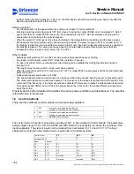
2
EA-
Threshold voltage 10VDC
3
EB+
Threshold voltage 10VDC
4
EB-
Threshold voltage 10VDC
5
+24V
+24VDC short circuit protected
6
0V
Common for encoder supply
28
ROC1
29 ROC1
Relay output, 250V 8A, normal open
Relay contact ROC1 closes when inverter is powered and no faults occurs
Relay contact ROC1 opens if the SSU has tripped in:
Overspeed
Speed difference
Zero speed
Relay test fault
Watch dog fault
LED Blinking
Status
Red 1Hz OK
Yellow 0.25Hz OK
Yellow
4Hz
Board internal fault or communication fault with control unit
1
2
3
4
ON OFF
S1
S2
S3
1 2 3 4 5 6
S1
S2
S3
RED
YELLOW
28 29
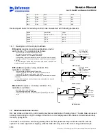
3.1.6 I/O Extension board (Slot D)
NXOPTB9 / I/O Extension board
ID: 52305691
Terminal Signal
name
Description
1 DID1
Not
used
2 DID2
42-240Vac
50/60Hz
3 DID3
42-240Vac
50/60Hz
4 DID4
42-240Vac
50/60Hz
5 DID5
42-240Vac
50/60Hz
6
COM
Common for DID1-DID5
7
ROD1
8 ROD1
Relay output, 250V 8A, normal open
For fan of braking resistor unit
The threshold voltage for digital inputs DID1-DID5 is 35VAC.
LED Blinking
Status
Yellow 0.25Hz OK
Yellow
4Hz
Board internal fault or communication fault with control unit
YELLOW
1
2
3
4
5
6
7
8
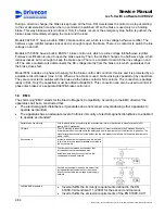
3.2 Control voltage transformer
Power of control voltage transformer has to be n * 50VA + 50VA (min. 250VA), n = number of inverters.
This power does not have to be added to otherwise needed transformer power.
3.3 Speed
sensors
3.3.1 Sensor
bearing
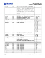
D2L needs information about the motor rotation speed for stall, speed difference and overspeed supervision.
Order codes of the bearing sensors are shown in the table below.
Motor type
Motor code
Pulses per revolution
Order code
Supply voltage
Max load
MF10MA200
T1
32
NM768NR3
24V DC
20 mA
MF10MB200
T2
32
NM768NR3
24V DC
20 mA
19/58
Drivecon Inc. reserves the right to alter or amend the above information without notice.
Содержание D2L
Страница 59: ......


