Service Manual
rev 5.0 with software Ind1V022
3.1.3 Basic I/O board (Slot A)
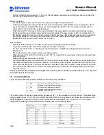
Basic I/O-Board is in CSU slot A. It has two board levels, one for electronics level signals (terminals 1-10) and
one for control voltage signals (42-240Vac).
NXOPTA6 / Basic I/O board
ID: 52288046
Terminal Signal
name Description
1 PUR Not
used
2
+15 V
Not used
3
AIN1+
Analog input 1 (0-10V)
4 AIN2+
Not
used
5
AIN-
Common for analog input and output signals
6 AOUT1
Not
used
7
AOUT2
Analog output 2 (0-10V)
8 DOA1
Not
used
9
0V
I/O ground terminal
10 +24V Not
used
11
S1
Digital input 42-240Vac 50/60Hz (Direction S1)
12
S2
Digital input 42-240Vac 50/60Hz (Direction S2)
13
DIA3
Digital input 42-240Vac 50/60Hz
14
DIA4
Digital input 42-240Vac 50/60Hz
15
DIA5
Digital input 42-240Vac 50/60Hz
16
OK
Digital input 42-240Vac 50/60Hz (OK-signal).
OK-input is connected straight to the ASIC.
Inverter is ready to operate when OK-signal is
active “1”.
17
COM
Common for 42-240Vac 50/60Hz
18
COM
Common for 42-240Vac 50/60Hz
1 2 3 4 5 6 7 8 9 10
11 12 13 14
15 16 17 18
The threshold voltage for digital inputs S1, S2, DIA3, DIA4, DIA5 and OK is 35VAC.
3.1.4 Relay / Thermistor board (Slot B)
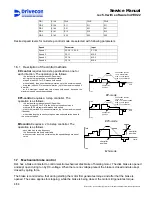
NXOPTA3 / Relay / Thermistor board
ID: 52305690
Terminal
Signal name
Description
21 ROB1
22 ROB1
23 ROB1
Relay output, 250V 8A
25
ROB2
26 ROB2
Relay output, 250V 8A, normal open
28 T1
29 T2
Thermistor input, double isolated,
R
trip
=4.7k
Ω
25 26
21 22 23
28 29
3.1.5 SSU Speed Supervision board (Slot C)
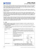
SSU is in CSU slot C, see chapter Speed supervision settings.
SSU / Speed supervision unit
ID: 52288044
Terminal Signal
name
Description
1
EA+
Threshold voltage 10VDC
18/58
Drivecon Inc. reserves the right to alter or amend the above information without notice.
Содержание D2L
Страница 59: ......


