MAINTENANCE
SECTION 5
Page 17
DRESSTA
OM515C520C99/1E
AIR CLEANING SYSTEM
INSTALLATION (Fig. 5.3)
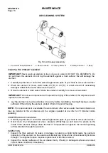
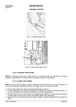
1. Insert the open end of the element into air cleaner body (5) over the safety element.
2. Install cover (1) and secure the cover to the body with the snap fasteners.
3. Inspect and tighten all air cleaner connections before resuming operation.
NOTE:
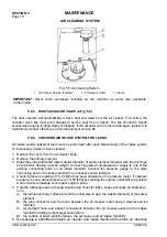
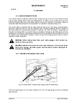
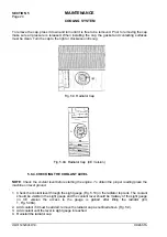
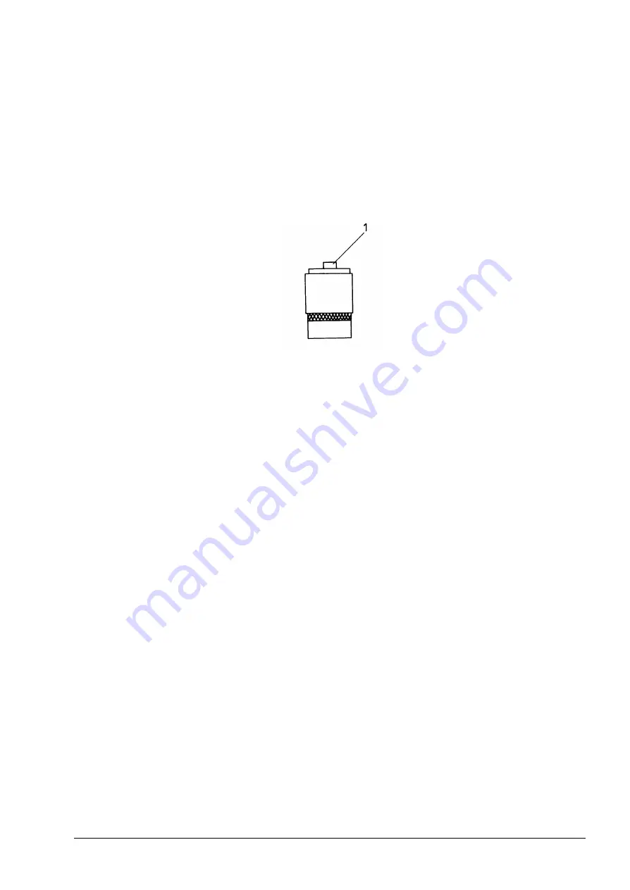
After servicing the filter element press reset button (1, Fig. 5.4.) to reset the air cleaner
service indicator (Fig. 5.5). The red strip should disappear after resetting.
Fig. 5.4. Air Cleaner Service Indicator
1. Reset button
4. Start the engine. If the air cleaner service indicator indicates air restriction, stop the engine and
replace the primary or primary and safety filter elements.
5.6.3. SAFETY (INNER) FILTER ELEMENT
Replace the safety element with every third change of the primary element or when plugged, as
shown by the service indicator.
REMOVAL (Fig. 5.3)
1. Remove the primary element as described above.
2. Pull safety element (4) out of the body.
3. Clean the inside of body (5) with a damp cloth. A small amount of nonsudsing detergent added
to the water will facilitate removal the soot.
INSTALLATION
1. Install new safety element (4) the open end first into body (5).
2. Install outer element (3) as described above.
5.6.4. PRECLEANER SCREEN
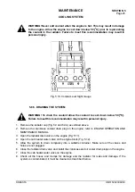
The dome of precleaner hood (2, Fig. 5.5.) serves as a rain shield and the screen prevents chaff
and course dirt from getting into the air cleaner. Keep this screen clean from all chaff, oil or dust.
Clogged holes in the screen will reduce the power of the engine by restricting the airflow.
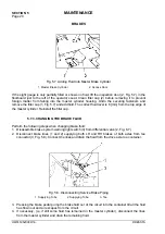
Loosen clamp screw (3, Fig. 5.5) on the precleaner hood. Twist and pull upward to remove the cap.
Use compressed air to clean the screen. If compressed air is not available, wash in clean hot water
or water containing a small amount of nonsudsing detergent.
Содержание 515C
Страница 3: ...OM515C520C99 1E DRESSTA ...
Страница 5: ......
Страница 7: ......
Страница 10: ...SECTION 1 INTRODUCTION ...
Страница 11: ...INTRODUCTION SECTION 1 DRESSTA OM515C520C99 1E SECTION CONTENTS 1 1 Introduction 3 1 2 Serial Numbers 5 ...
Страница 12: ......
Страница 17: ...SECTION 2 SAFETY PRECAUTIONS ...
Страница 19: ......
Страница 37: ...SECTION 3 MACHINE TRANSPORT AND STORAGE ...
Страница 39: ......
Страница 49: ...SECTION 4 OPERATING ...
Страница 51: ......
Страница 55: ...SECTION 4 OPERATING Page 6 OM515C520C99 1E DRESSTA UNIVERSAL SYMBOLS FOR INSTRUMENTS AND CONTROLS ...
Страница 107: ...SECTION 5 MAINTENANCE ...
Страница 165: ...SECTION 6 SPECIFICATIONS ...
Страница 167: ......
Страница 181: ...SECTION 6 SPECIFICATIONS Page 16 OM515C520C99 1E DRESSTA WIRING DIAGRAMS ...
Страница 182: ...SPECIFICATIONS SECTION 6 Page 17 DRESSTA OM515C520C99 1E WIRING DIAGRAMS ...
Страница 187: ...SECTION 6 SPECIFICATIONS Page 22 OM515C520C99 1E DRESSTA WIRING DIAGRAMS ...
Страница 192: ...SPECIFICATIONS SECTION 6 Page 27 DRESSTA OM515C520C99 1E SPECIFICATIONS Fig 6 10A Overall Dimensions Wheel Loader 520C ...

