

Installation Instructions
505501 Outdoor Volleyball System by Draper
Caution
➀
Inspect all contents prior to installation. Report any missing parts to
dealer
immediately.
➁
The net is designed to fit by customizing the length of the top rope. Tie
a loop in one end of the top rope at a location that allows proper ten-
sioning. Do not cut the excess rope until you are confident you have
the correct length. Length will depend on the distance between the
standards. Nets cannot be returned after unwrapping.
➂
Read all instructions before proceeding.
Bill of Materials
A (2) Volleyball Standards
H (4) Rope Ratchet Tensioners
B (1) Cable Tensioning Slider Bar Assembly (Packaged w/Net)
C (1) Non-Tensioning Slider Bar Assembly I (2) 505309 Ground Sleeve
D (2) Height Labels
with cap (if applicable)
E (1) Label Squeegee
J (1) 505310 Sand/Beach
F (2) Stop Bolt and Nut (pre-installed)
Install Kit (if applicable)
G (1) Net
K (1) Carabineer
Immediately unpack all components and cross check against bill of materials.
Please Note:
Consult Draper’s Equipment Rules and Court Diagrams Guide
to determine proper location of post and/or Ground Sleeves.
➀
If applicable, follow instructions and drawings provided with ground sleeves
(I) or sand/beach installation kit (J), then skip to step 4.
➁
If placing the posts for a permanent installation you should dig a hole
measuring 12" minimum diameter x 24" deep. (Note: if you live an area
where the frost line is below 24", it is advisable to dig to below the normal
frost
line.)
➂
Fill the hole with wet premix concrete, insert pole leaving a minimum of
102" above the playing surface. Posts should be installed with the extruded
grove for the slider bar facing toward center court. Vibrate post to settle
concrete around post and release any trapped air pockets. Make sure post
is straight and plumb then brace post while concrete is drying. Allow 24
hours minimum drying time before continuing assembly.
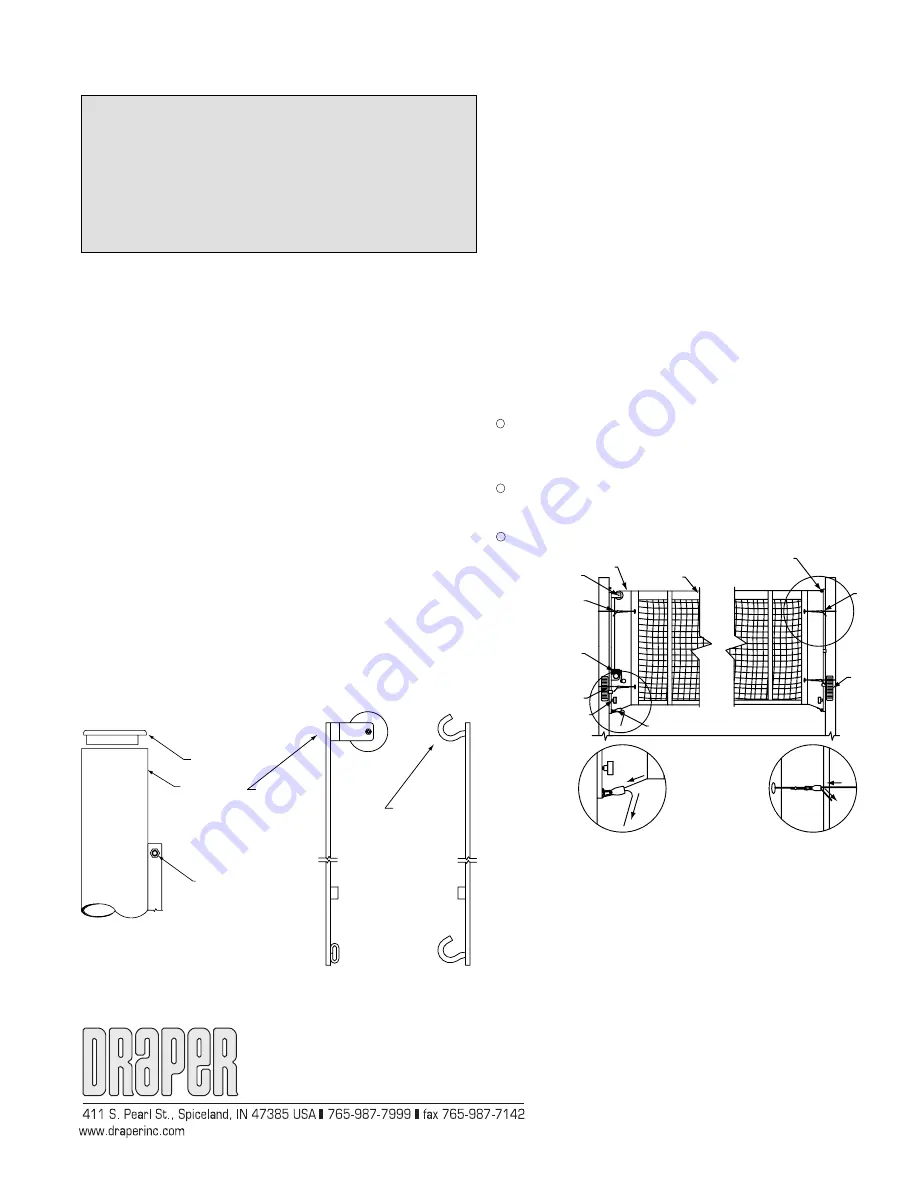
➃
Remove the top cap and stop screw to install the slider bar assemblies (B)
and (C) into the standards (A) from the top (Fig. 1). Note which end is the
top of the slider bars (Fig. 2). Replace bolt and nut or cap and screw to
keep slider bar in place during transport.
Figure 1
Figure 2
Top Cap
Stop Screw
Stop Bolt
and Nut
Top of
Non-Tensioning
Slider Bar Assy
Top of
Cable Tensioning
Slider Bar Assy
Copyright © 2005 Draper Inc.
Form 505501-OutdoorVolleyball_Inst05
Printed in U.S.A
➄
Uncoil approximately 24" of the web strap from the winch to allow for net
tensioning.
➅
Attach the kevlar top rope to the slider bars (B) and (C). On the cable
tensioning slider bar (B), the rope will loop over the pulley and attach to
the spring clip on the end of the winch strap. On the non-tensioning slider
bar (C) attach the loop to the hook on the top of the slider bar (Fig. 3).
➆
Tension the top rope by tightening the net top tension winch.
➇
Attach the loop on one end of the bottom rope to the hook on the bottom
of the slider bar. Attach the other end of the bottom rope with the spring
hook on the rope ratchet. Tension the bottom rope by pulling the rope
through the bottom rope ratchet tensioner (H) (Fig. 3).
➈
Loop two small rope ratchet assemblies (H) around each standard and
through the eyelets on the net side tapes. Tension the net sides by pulling
the end of the ropes. Release the rope ratchet by pressing on the release
button. Ratchets should be rotated close to the pole and behind the
padding to prevent contact with players (Fig. 3).
➉
Once the net is attached it must be adjusted to its desired height. Loosen
the winch to release the net tension. Do this before moving the slider bars
(Fig.
3).
11
After the net tension has been released, loosen the slider bar locking
knobs to allow the slider bars to freely move up and down. Adjust net to
desired height. Once the top of the net is at the desired height, tighten the
slider bar locking knobs and net top tension winch.
12
Once the net is locked and tensioned at the desired height, install the
height labels (D). Line up the appropriate line on the height label with the
orange height indicator arrow.
13
Install padding and antennas.
Figure 3
Top Cable
Net
Non-Tensioning Slider Bar
Tensioning Slider Bar
Rope Ratchet Tensioners
Net Top Tension Crank
Height Indicator Arrow
Slider Bar Locking Handle
Height Label
Detail A
Detail B
Detail B
Detail A
Содержание 505501
Страница 2: ......