45 / 96
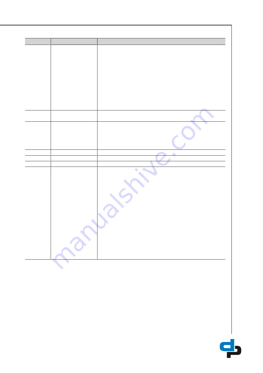
Table 19:
Symbols for information on the system
Position
Refers to
Description
1
Display for suction-side
sensors
Depending on the connected sensors the following values are displayed:
–
Version with pressure gauge:
Displays the pressure at the inlet of the
pressure booster system.
–
Version with pressure switch / float switch / flow monitor:
Displays the
digital input signal Hi or Lo.
If several sensors are used, the values are displayed alternately.
– PIN display
– For connecting the control unit to the mobile device. (The
complete PIN is composed of this PIN and the PIN in
position 7.)
– Display of the firmware version (The total firmware version is composed of
the numbers in this position and in position 7.)
2
Suction-side sensor
The corresponding values are shown in position 1.
The corresponding messages are shown in position 7.
3
Display for the pump(s)
If applicable, a frequency inverter is displayed in the upper area.
– The corresponding messages are shown in position 7.
The pump is displayed in the lower area. The impeller vanes of the pump
displayed rotate when one or several pump sets in the system are running.
– The corresponding messages are shown in position 7.
4
Discharge-side sensor
The corresponding values and messages are shown in position 7.
5
Accumulator
The corresponding messages are shown in position 7.
6
Temperature measurement
The corresponding values and messages are shown in position 7.
7
Display for the discharge
side
– Displays information on the selected pump set
– Pump load
– Pump speed
– Pump-specific messages
– Displays information on the pressure booster system
– Discharge-side pressure
– Temperature
– Messages
– PIN display
– For connecting the control unit to the mobile device. (The
complete PIN is composed of this PIN and the PIN in
position 1.)
– When the screen is unlocked
– Display of the firmware version. (The complete firmware version is
composed of this number and the number in position 1)
7.3 Operating the device via the control panel
The following functions are available on the control panel of the control unit:
– Unlocking the screen [
– Changing the operating mode [
– Activating the Bluetooth connection [
Содержание Hydro-Unit Utility Line F
Страница 29: ...29 96 1 2 Fig 12 PE connection 1 Earthing terminal 2 Location of power connection ...
Страница 58: ...58 96 ...
Страница 92: ...92 96 T Tank 79 Timers 73 W Warnings 9 Warranty claims 7 ...
Страница 93: ......
Страница 94: ......
Страница 95: ......


